
Wireless microphone with antenna therein

a wireless microphone and antenna technology, applied in the direction of microphone structure association, mouthpiece/microphone attachment, transducer details, etc., can solve the problems of inability to take stable antenna ground and inability to obtain good rf (radio frequency) performance, and achieve good rf performance and stable antenna ground. , the effect of good radio wave radiation efficiency

Active Publication Date: 2017-08-29
AUDIO-TECHNICA
View PDF14 Cites 2 Cited by
  • Summary
  • Abstract
  • Description
  • Claims
  • Application Information

AI Technical Summary

Benefits of technology

The wireless microphone described in this patent has an antenna in the lower part of the main body. The purpose of the invention is to provide a microphone that has good RF performance, stable antenna ground, and can be easily gripped by the user with a palm of their hand. This allows for a better user experience and increases the efficiency of the microphone's operation.

Problems solved by technology

Consequently, there are problems in that, even when the cover member is gripped, stable antenna ground cannot be taken, and good RF (Radio Frequency) performance cannot be obtained.

Method used


Image

  • Wireless microphone with antenna therein
  • Wireless microphone with antenna therein
  • Wireless microphone with antenna therein

Examples


Embodiment Construction

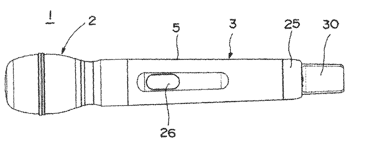
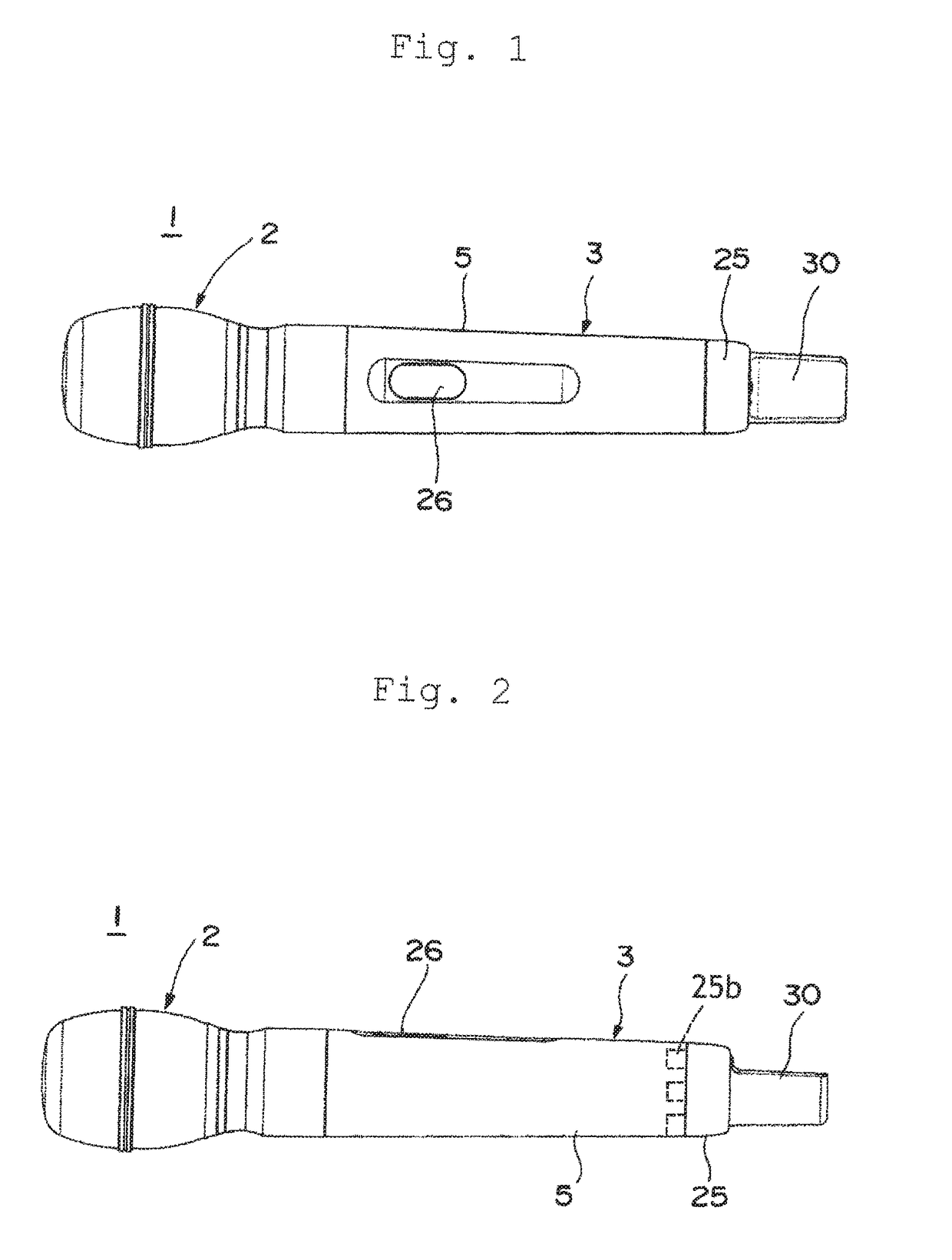
[0026]Hereinafter, an embodiment of the present invention will be described based on drawings. FIG. 1 is a plan view of a wireless microphone according to the present invention, and FIG. 2 is a side view thereof.

[0027]An illustrated wireless microphone 1 is configured by a microphone head 2 that incorporates a microphone unit for performing sound collection and a microphone main body 3 detachably provided to this microphone head 2. Further, the wireless microphone 1 includes an antenna part 30 (an antenna circuit) for wirelessly outputting an audio signal in a rear part of the microphone main body 3, and a display window 26 is provided on an outer peripheral surface thereof.

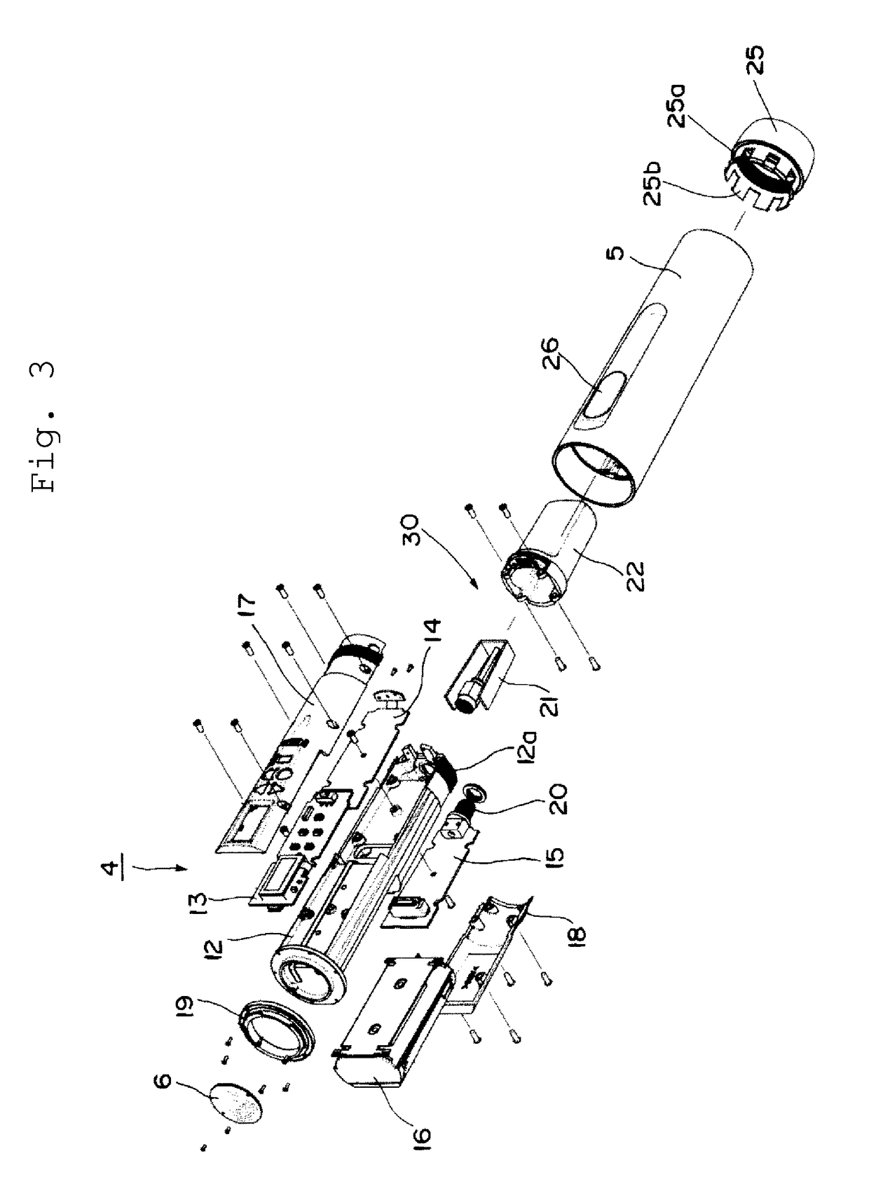
[0028]The microphone main body 3 is configured by a main body member 4 formed of a plurality of boards or the like and a cylindrical cover member 5 made of metal (e.g., made of aluminum) for accommodating this main body member 4.

[0029]FIG. 3 is a perspective view illustrated by disassembling the microphone main b...


PUM


Abstract

In a wireless microphone having an antenna in a lower part of a main body, a wireless microphone in which a microphone main body serves as a ground plane, which secures stable antenna ground by being gripped by a user, and which is capable of obtaining good RF performance is provided. The microphone main body includes a holder member made of metal for holding at least an antenna circuit part, a cylindrical cover member made of metal for covering a periphery of the holder member, and a cylindrical grip end member made of metal, inserted into a rear end side of the cover member, and connected with a rear part side of the holder member. The holder member has conduction with the cover member via the grip end member.

Description

RELATED APPLICATIONS[0001]The present application is based on, and claims priority from, Japanese Application No. JP2014-231261 filed Nov. 14, 2014, the disclosure of which is hereby incorporated by reference herein in its entirety.BACKGROUND OF THE INVENTION[0002]Field of the Invention[0003]The present invention relates to a wireless microphone, and particularly to a wireless microphone having an antenna in a rear part of a microphone main body.[0004]Description of the Related Art[0005]Conventionally, a wireless microphone includes a microphone head that accommodates a microphone unit for performing sound collection and a microphone main body connected with this microphone head.[0006]The microphone main body is formed by a holder member (a body) for holding a circuit board, a battery, an antenna, and the like and a cover member for covering this holder member (a gripping case portion). When the holder member is connected with the cover member, the circuit board, the battery, and th...

Claims


Application Information

Patent Timeline
Patent Type & Authority Patents(United States)
IPC IPC(8): H04R25/00H04R1/04H04R1/08H04R1/06
CPCH04R1/04H04R1/06H04R1/083H04R2420/07
Inventor NAITO, YOSHIHIKOMASUDA, AKIRA
Owner AUDIO-TECHNICA
Learn More