
Thermal Barrier Coated RF Radomes

a technology of thermal barrier and radome, which is applied in the field of radomes, can solve the problems of reducing thermal properties, affecting the performance of radomes, and reducing the thermal properties of radomes, so as to enhance the thermal environment surviveability of radomes, enhance the performance of radomes, and enhance the all weather flight capability of radomes

Active Publication Date: 2014-10-09
THE BOEING CO
View PDF0 Cites 21 Cited by
  • Summary
  • Abstract
  • Description
  • Claims
  • Application Information

AI Technical Summary

Benefits of technology

[0012]This need for RF radomes and method is satisfied. Unlike known devices and methods, embodiments of the RF radomes and method may provide one or more of the following advantages: provides RF radomes with thermal barrier coatings that enhance performance of the RF radomes in high temperature applications, enhance all weather flight capability of the RF radomes, and enhance thermal environment surviveability of the RF radomes; provides thermal barrier coated RF radomes that do not significantly degrade signal transmission in RF radomes, that extend a flight performance envelope for a given radome material, that expand flight envelopes for increased, longer duration aero-heating, and that reduce radome exposure temperatures; provides thermal barrier coated RF radomes that allow for lower cost material substitutions, that reduce thermal stresses by lowering thermal gradients along the length and through the thickness of the radome, and that provide subsonic erosion protection in captive carry; provides thermal barrier coated RF radomes that provide protection from handling loads and low velocity impacts, that provide sacrificial erosion protection in supersonic and hypersonic flights, that reduce radome life cycle costs, and that improve survival and absorb impact energy from encounters with rain, snow, fog, atmospheric particles, dust particles, and other environmental elements and conditions to prevent failures of the radomes; provides thermal barrier coated RF radomes that reduce thermal load on internal electronics for improved electrical and guidance reliability, improve overall survivability of radomes and flight vehicles, permit extended duration flights, and apply to multiple candidate radome materials; provides thermal barrier coated RF radomes having enhanced performance in high temperature applications, such as temperatures over 400 degrees Fahrenheit; provides thermal barrier coated RF radomes that may result in a flight vehicle with increased speed capability, lower cost, robust and improved mission reliability such as targeting reliability, and improved system effectiveness.
[0013]In an embodiment of the disclosure, there is provided a method for coating a radio frequency (RF) radome. The method comprises providing a radio frequency (RF) radome. The method further comprises applying a thermal barrier coating having a dielectric constant less than about 2.0 onto a surface of the radome to form a thermal barrier coated RF radome. The thermal barrier coating reduces a structure temperature of the RF radome by greater than 300 degrees Fahrenheit to enhance thermo-mechanical properties and performance of the RF radome.
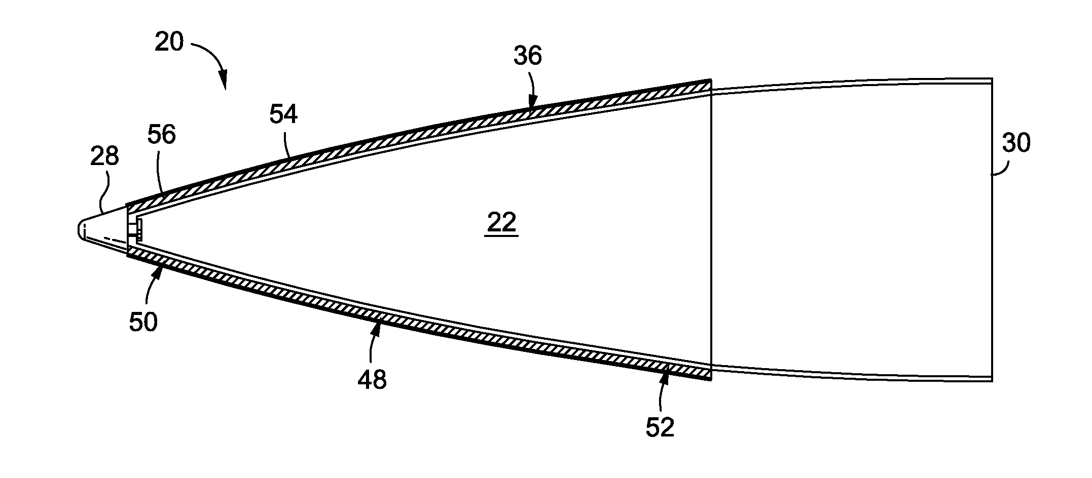
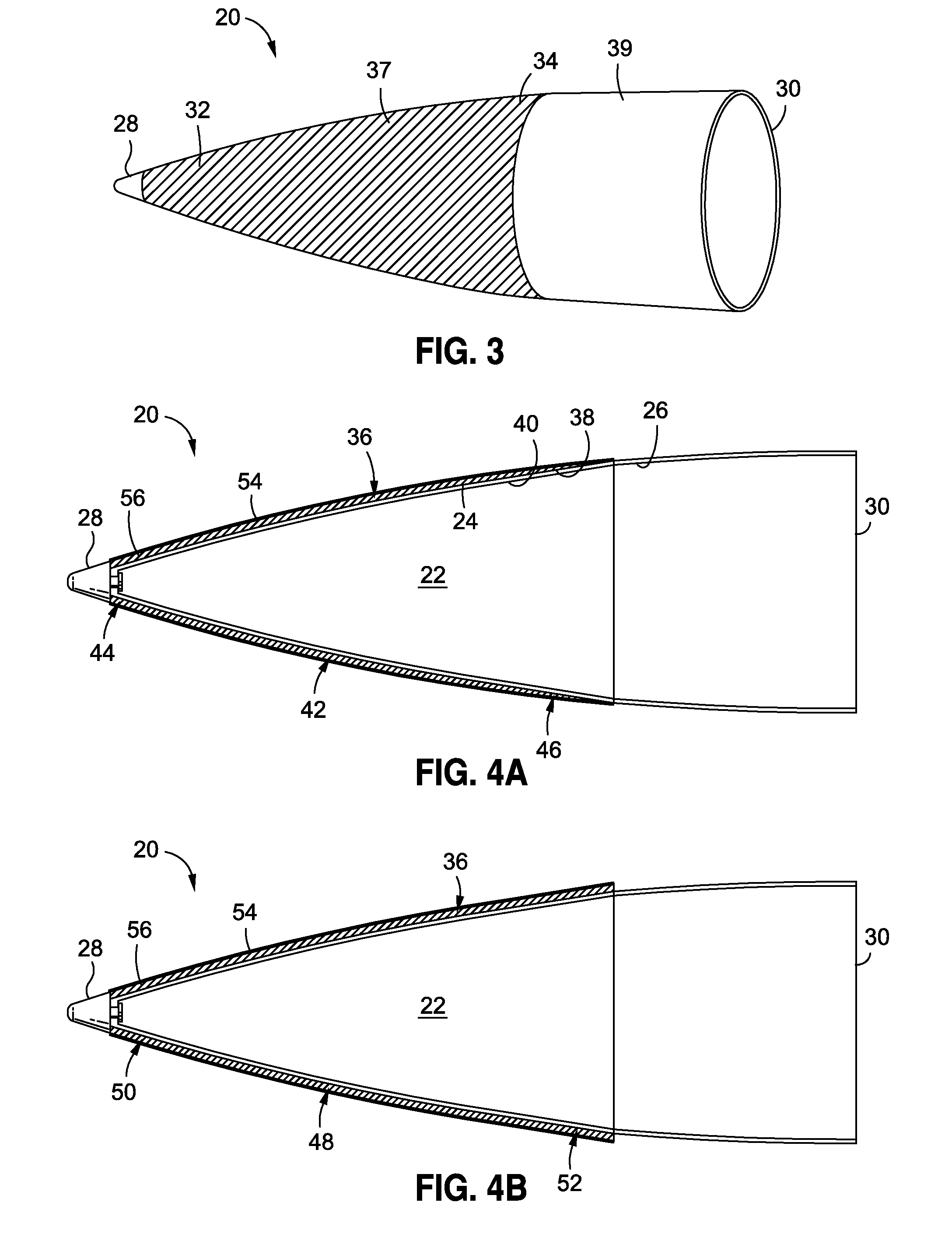
[0015]In another embodiment of the disclosure, there is provided a thermal barrier coated radio frequency (RF) radome. The radome comprises a radio frequency (RF) radome comprising an exterior surface, an interior surface, a tip, and a base, wherein the RF radome is designed to transmit RF signals. The radome further comprises a thermal barrier coating applied to an exterior surface of the radome. The thermal barrier coating has a dielectric constant of less than about 2.0. The thermal barrier coating reduces a structure temperature of the RF radome by greater than 300 degrees Fahrenheit to enhance thermo-mechanical properties and performance of the RF radome.

Problems solved by technology

The surfaces of high speed aircraft, missiles, supersonic airframes, spacecraft, and other craft are often subjected to aerodynamic heating, extreme environmental conditions, and significant mechanical stresses and erosion, which can all affect their performance.
Such materials, however, are generally more expensive and may be subject to various limitations.
However, such radomes may have reduced thermal properties and reduced erosion resistance in high speed flight.
In addition, excessive temperature can cause PMCs to decompose during flight.
Such decomposition may lead to surface roughness which can increase drag and aerodynamic heating and increase deterioration in signal transmission.
However, radomes made of CMC can be more expensive than radomes made of PMCs.
Radomes made of CMCs may have reduced erosion resistance which may result in excessive material or ply loss.
CMC radomes can have significant porosity which may result in fluid intrusion into the radome, may outgas during flight, and may have reduced RF transmission properties.
However, radomes made of monolithic ceramics can be significantly more expensive to produce than radomes made of PMCs or CMCs.
Such radomes made of monolithic ceramics may require machining on green ceramics and / or grinding of fully hardened ceramics to achieve precision dimensional control which can result in increased production costs and lower yields.
Moreover, radomes made of monolithic ceramics may have less robust performance from impact shock loads or high internal stresses from large internal temperature gradients.
Radomes made of monolithic ceramics typically have higher dielectric and loss properties that reduce the effectiveness of signal transmission compared to radomes made of PMCs or CMCs.
Thus, existing materials may be expensive and may be subject to reduced performance and surviveability under extended high temperature exposures (e.g., above 400 degrees Fahrentheit), severe thermal gradients, and extreme weather or atmospheric conditions.
It is believed that known RF radomes do not use thermal barrier coatings to enhance or extend radome performance capabilities.

Method used


Image

  • Thermal Barrier Coated RF Radomes
  • Thermal Barrier Coated RF Radomes
  • Thermal Barrier Coated RF Radomes

Examples


Embodiment Construction

[0033]Disclosed embodiments will now be described more fully hereinafter with reference to the accompanying drawings, in which some, but not all of the disclosed embodiments are shown. Indeed, several different embodiments may be provided and should not be construed as limited to the embodiments set forth herein. Rather, these embodiments are provided so that this disclosure will be thorough and complete and will fully convey the scope of the disclosure to those skilled in the art.

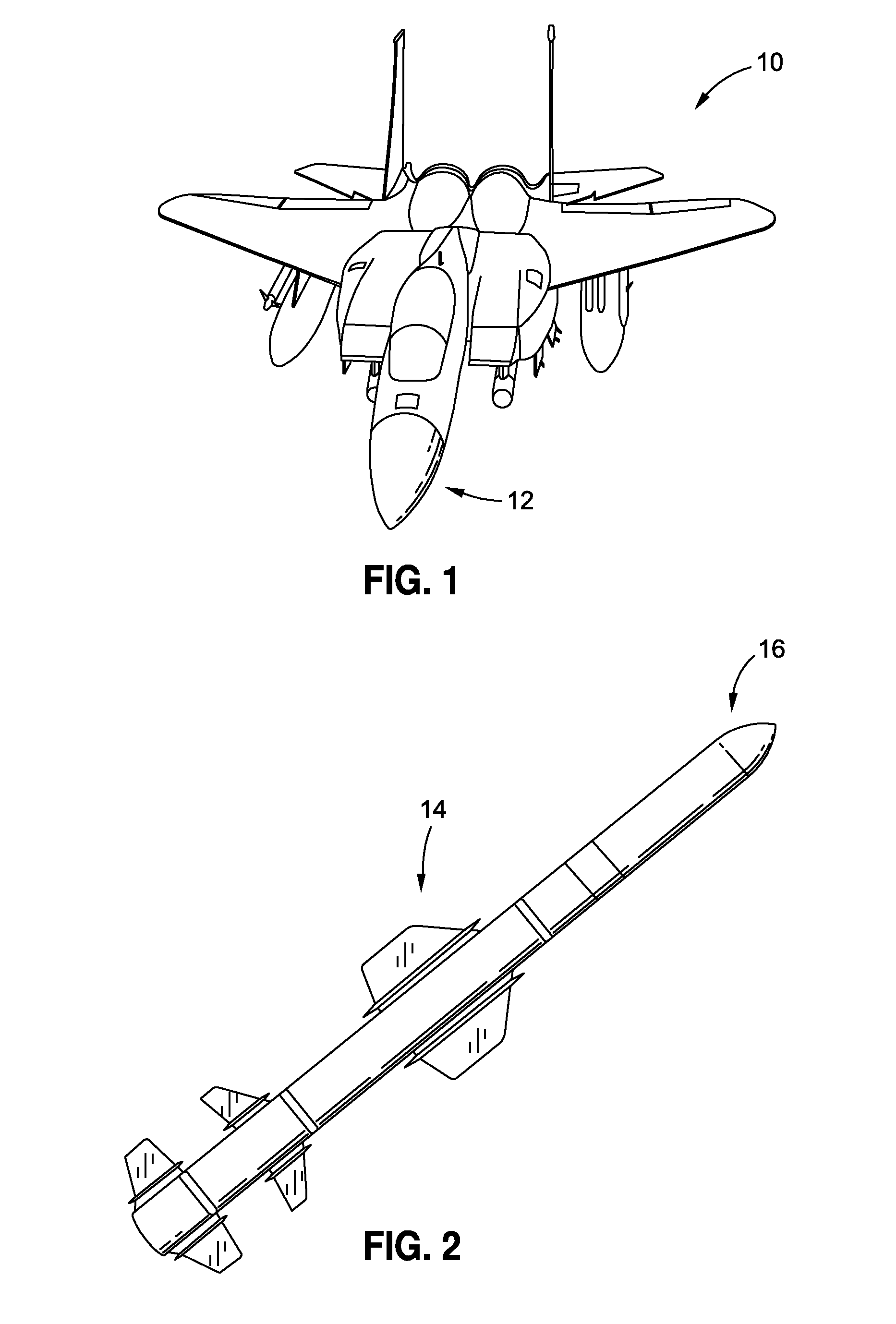
[0034]FIG. 1 is an illustration of a front perspective view of an aircraft 10 having an exemplary RF radome 12 that may be coated using the thermal barrier coatings disclosed herein. FIG. 2 is an illustration of a side view of a missile 14 having an exemplary RF radome 16 that may be coated using the thermal barrier coatings disclosed herein. Preferably, the thermal barrier coatings disclosed herein may be used to coat high speed RF radomes used in high speed aircraft, missiles, supersonic airframes, space...


PUM


Abstract

A thermal barrier coated radio frequency (RF) radome is provided having a radio frequency (RF) radome with an exterior surface, an interior surface, a tip, and a base, wherein the RF radome is designed to transmit RF signals. A thermal barrier coating is applied to an exterior surface of the radome, wherein the thermal barrier coating has a dielectric constant of less than about 2.0, and further wherein the thermal barrier coating reduces a structure temperature of the RF radome by greater than 300 degrees Fahrenheit to enhance thermo-mechanical properties and performance of the RF radome.

Description

CROSS-REFERENCE TO RELATED APPLICATIONS[0001]The present application is a divisional of and claims priority to pending application Ser. No. 12 / 629,044, filed Dec. 1, 2009, entitled THERMAL BARRIER COATED RF RADOMES AND METHOD, the entire contents of which is incorporated herein by reference.BACKGROUND[0002]1) Field of the Disclosure[0003]The disclosure relates to radomes, and in particular, to radio frequency (RF) radomes used at high temperatures.[0004]2) Description of Related Art[0005]RF (radio frequency) radomes are structures that may be used on high speed aircraft, missiles, supersonic airframes, spacecraft, and other craft. RF radomes are typically used to cover instruments, such as radar devices and antennas, that transmit and receive electromagnetic and RF radiation, in order to protect such devices from environmental conditions and mechanical stresses. RF radomes are constructed to be substantially transparent to RF radiation over broadband or narrowband frequencies. The s...

Claims


Application Information

Patent Timeline
Patent Type & Authority Applications(United States)
IPC IPC(8): H01Q1/42B64C1/36B64C30/00B64C7/00
CPCB05D7/00B05D1/38B64C30/00B64C1/36B64C7/00H01Q1/42H01Q1/422H01Q1/02H01Q1/28
Inventor WALDROP, III, JOHN C.DRIEMEYER, DANIEL E.RIEGEL, LAURA S.LAWTON, STANLEY A.
Owner THE BOEING CO
Learn More