

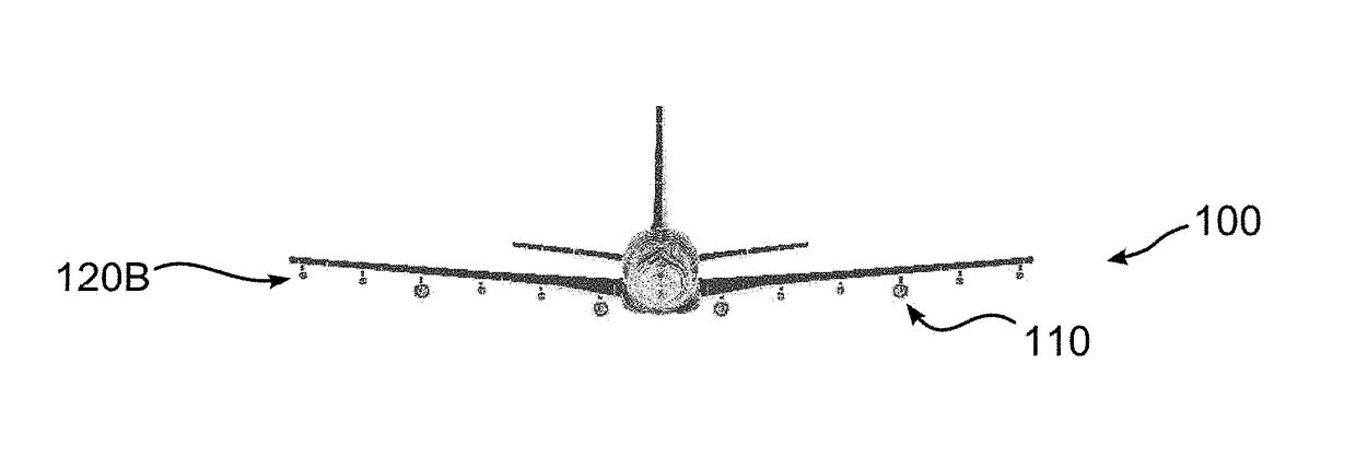
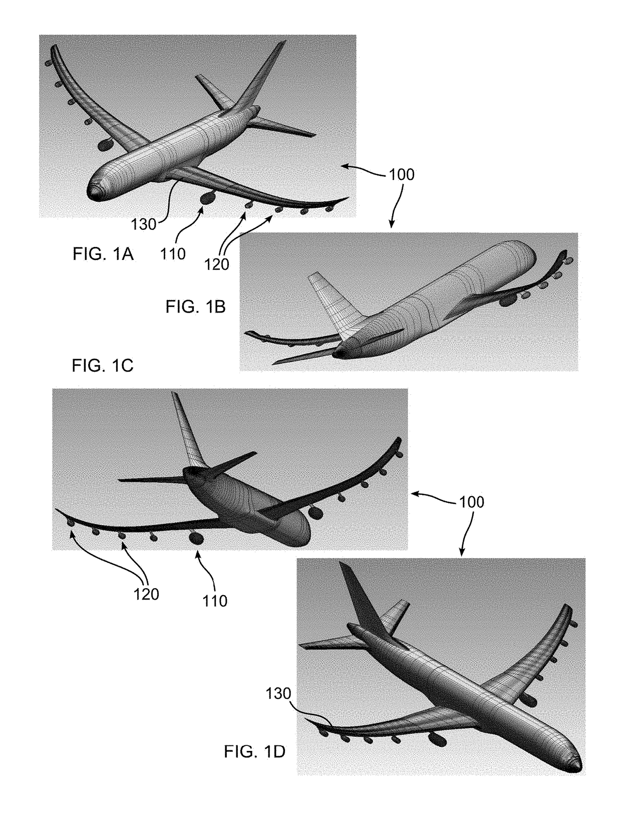
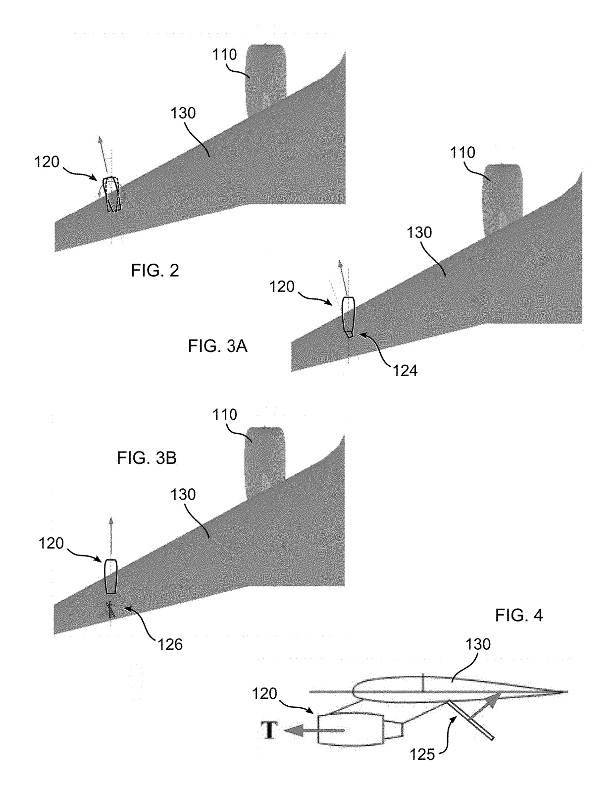
Aeroelastic wing shaping using distributed propulsion
a distributed propulsion and aeroelastic technology, applied in the direction of efficient propulsion technologies, aircraft navigation control, transportation and packaging, etc., can solve the problems of helios pitching up and climbing, and achieve the effects of maintaining aeroelastic stability, improving l/d, and maintaining lift of aircra
- Summary
- Abstract
- Description
- Claims
- Application Information
AI Technical Summary
Benefits of technology
Problems solved by technology
Method used
Image

Examples
Embodiment Construction
[0096]As required, detailed embodiments are disclosed herein; however, it is to be understood that the disclosed embodiments are merely examples and that the systems and methods described below can be embodied in various forms. Therefore, specific structural and functional details disclosed herein are not to be interpreted as limiting, but merely as a basis for the claims and as a representative basis for teaching one skilled in the art to variously employ the present subject matter in virtually any appropriately detailed structure and function. Further, the terms and phrases used herein are not intended to be limiting, but rather, to provide an understandable description of the concepts.
[0097]The terms “a” or “an”, as used herein, are defined as one or more than one. The term plurality, as used herein, is defined as two or more than two. The term another, as used herein, is defined as at least a second or more. The terms “including” and “having,” as used herein, are defined as comp...
PUM
 Abstract
Description
Claims
Application Information