Evaporative emissions canister having an internal insert

a technology of evaporative emissions and canisters, which is applied in the direction of fuel injection apparatus, non-fuel substance addition to fuel, charge feed systems, etc., can solve the problem of reducing the total volume of carbon required for the canister, and achieves path-length sensitive effects, increased l/d, and reduced carbon requirements

Active Publication Date: 2006-05-30
DELPHI TECH IP LTD
View PDF8 Cites 23 Cited by
  • Summary
  • Abstract
  • Description
  • Claims
  • Application Information

AI Technical Summary

Benefits of technology

[0013]In a first embodiment in accordance with the invention, after the vapors flow through the hollow cylinder column of carbon adsorbent, the flow is directed through holes in the flange and out through the atmosphere port. The path for fuel vapors to flow along the hollow cylinder has a much increased L / D ratio as compared to the ratio for a solid cylinder of comparable length. This arrangement also reduces the total volume of carbon required for the canister.
[0014]In a second embodiment, the chamber is provided with a thin cylindrical tube surrounding the atmosphere port and extending into the insert. Flow through the flange cannot escape directly to the atmosphere port as in the first embodiment but rather is forced along a tortuous path between the cylindrical tube and the insert wall, makes a 180° turn at the end of the tube, and then again flows the length of the tube before reaching the atmosphere port. The tortuous path reduces flow of hydrocarbons from the carbon beds to atmosphere, especially diurnal emissions which are driven only by diffusion and therefore are path-length sensitive.

Problems solved by technology

This arrangement also reduces the total volume of carbon required for the canister.

Method used


Image

  • Evaporative emissions canister having an internal insert
  • Evaporative emissions canister having an internal insert
  • Evaporative emissions canister having an internal insert

Examples


embodiment 210

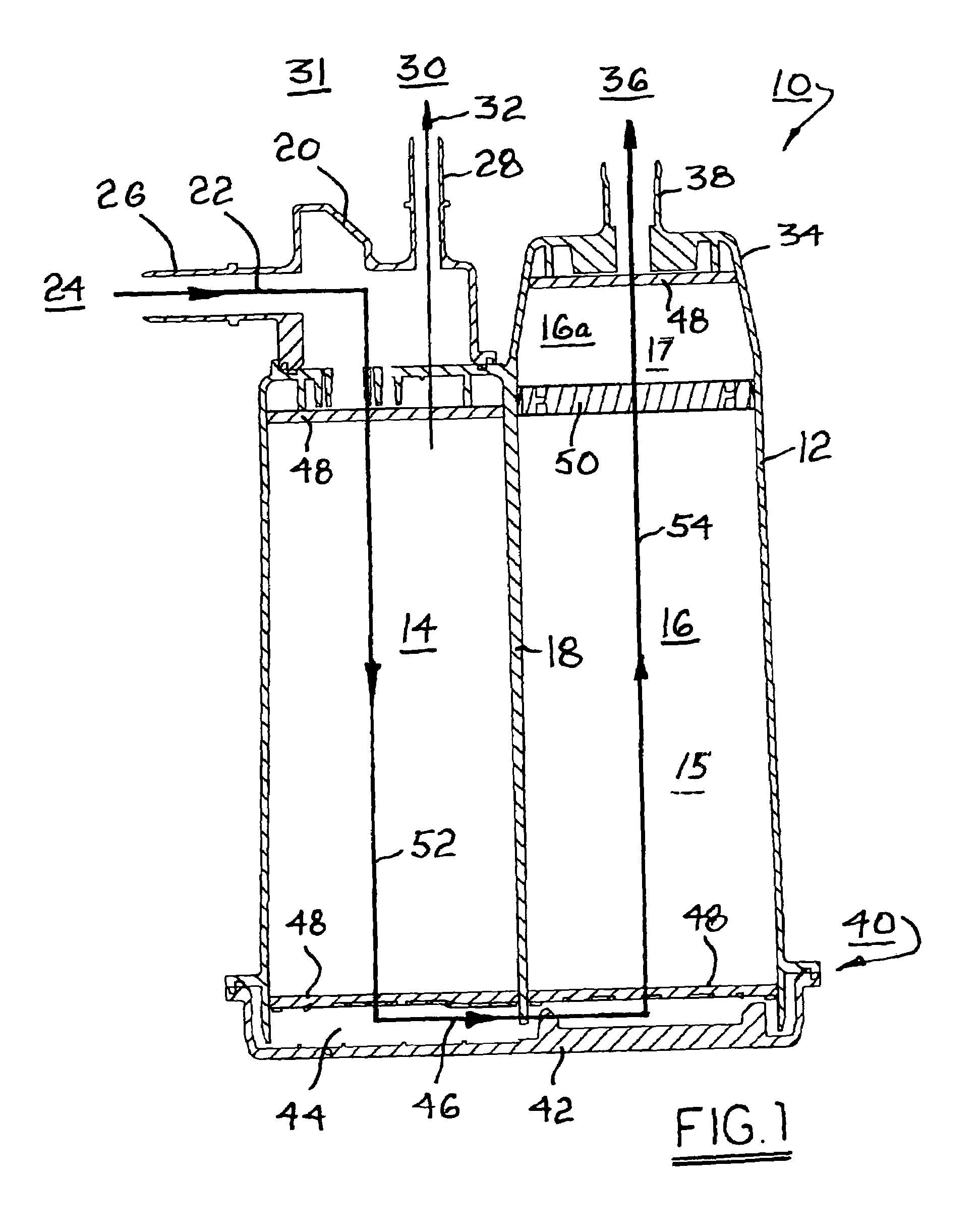
[0051]An important manufacturing advantage of canister embodiment 210 is that it provides a common platform for either LEV II or PZEV applications simply by adding or omitting scrubber 390. No other changes are required and the footprint within a vehicle is identical.
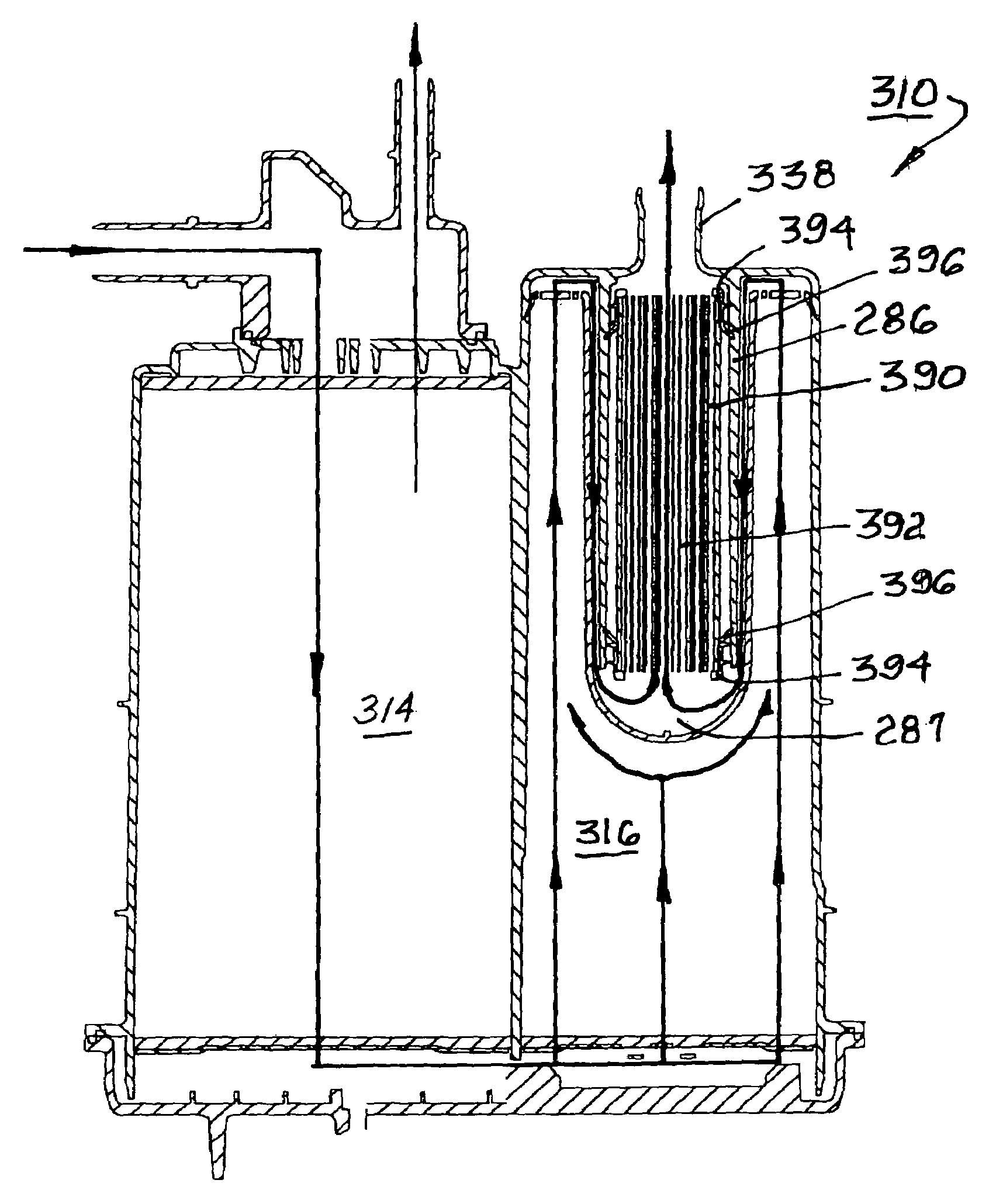
embodiment 310

[0052]Scrubber 390 is inserted into cylindrical tube 286 during assembly of embodiment 310 and must be retained in place during the working lifetime of the canister. First and second retaining seals 394 may be installed at the periphery of each end of scrubber 390, seals 394 having flexible wipers 396 similar to insert wipers 180 for centering the scrubber within the canister. Alternatively, the scrubber may be retained by annular polymeric gaskets (not shown), which may be formed in known fashion from a cross-linkable elastomeric composition such as a silicone and may be installed with the scrubber in liquid form prior to becoming cross-linked.

[0053]Because a scrubber formed as a carbon monolith is relatively fragile and easily damaged, such a scrubber is vulnerable to shock and vibration. In addition, silicone elastomers such as Viton are known to exhibit relatively high coefficients of thermal expansion. Under cold start conditions, for example, in the arctic, a scrubber could be...


PUM


Abstract

An emissions control canister including an insert having an elongate well and flange. The insert extends into a chamber such that a carbon adsorption column is a hollow cylinder around the insert. After vapors flow through the column of adsorbent, flow is directed through holes in the flange and out through an atmosphere port. The flow path through the hollow cylinder has an increased L / D ratio and improves emission performance. In a second embodiment, a cylindrical tube surrounds the exit port and extends into the insert, forcing vapor flow along a tortuous path between the cylindrical wall and the insert. In a third embodiment, a final scrubber is added inside the tube.

Description

TECHNICAL FIELD[0001]The present invention relates to a device for controlling evaporative emissions from vehicles; more particularly, to a device for controlling hydrocarbon emissions during refueling and shutdown; and most particularly, to a carbon-filled canister having a cap-shaped internal insert resulting in an improved emissions flow path through the canister in both fill and purge modes.BACKGROUND OF THE INVENTION[0002]Canisters for controlling evaporative emissions from vehicles are well known. Such emissions are created at two particular times: first, while a vehicle is being refueled, and vapor-laden air is being displaced from the fuel tank (known in the art as “refueling emissions”); and second, while a vehicle is shut down for an extended period, and fuel-laden adsorber in a canister spontaneously degases to the atmosphere (known in the art as “diurnal emissions” or “bleed” emissions).[0003]In the prior art, refueling emissions are collected typically by a canister dis...

Claims


Application Information

Patent Timeline
Patent Type & Authority Patents(United States)
IPC IPC(8): F02M37/04
CPCF02M25/0854F02M2025/0863
Inventor MEILLER, THOMAS C.SHNEYDMAN, ALEXANDER E.
Owner DELPHI TECH IP LTD
Why Eureka
Try Eureka