AI technical title is built by PatSnap AI team. It summarizes the technical point description of the patent document.
a technology of concrete and forming system, which is applied in the direction of construction, construction, and form/shutter/falsework, can solve the problems of cast-in-place concrete, high cost of concrete formwork, and other materials used in building construction, and achieves the effect of facilitating the placement of concrete roofs, facilitating sliding, and strengthening walls
Inactive Publication Date: 2017-09-12
KREIZINGER KENNETH ROBERT
View PDF30 Cites 0 Cited by
Summary
Abstract
Description
Claims
Application Information
AI Technical Summary
This helps you quickly interpret patents by identifying the three key elements:
Problems solved by technology
Method used
Benefits of technology
Benefits of technology
The scaffold forming system uses external braces called scaffold frames and walsers to support the form during construction. This eliminates the need for additional internal bracing. Additionally, the scaffold forming system can be used to create a concrete soffit around the exterior perimeter of a wall, which strengthens the wall and helps support a concrete roof.
Problems solved by technology
However, cast-in-place concrete has two major drawbacks.
Second, concrete formwork is expensive, due in large part by the use of form ties, and this higher cost results in buildings being built using other materials and / or systems.
Method used
Image
Click on the blue label to locate the original text in one second.
Reading with bidirectional positioning of images and text.
Examples
Embodiment Construction
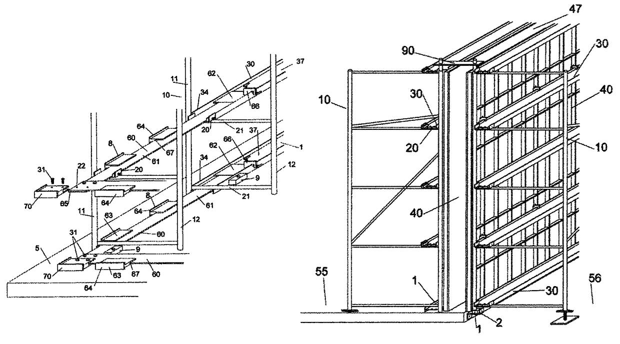
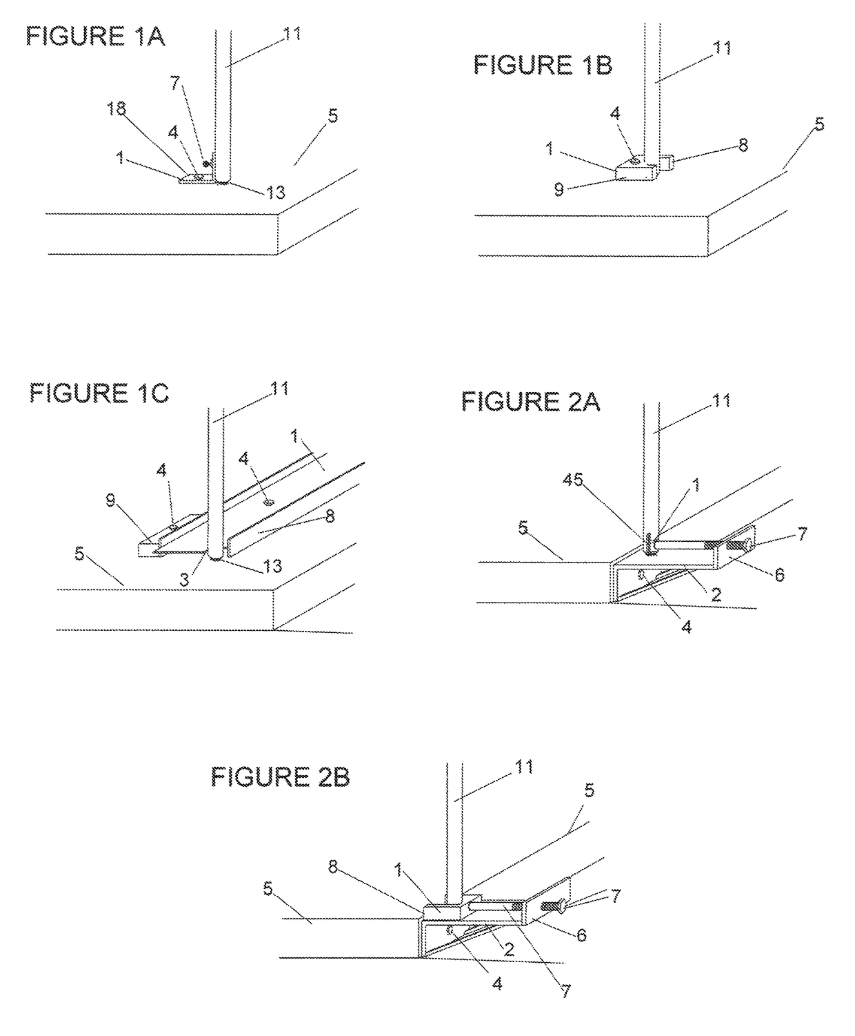
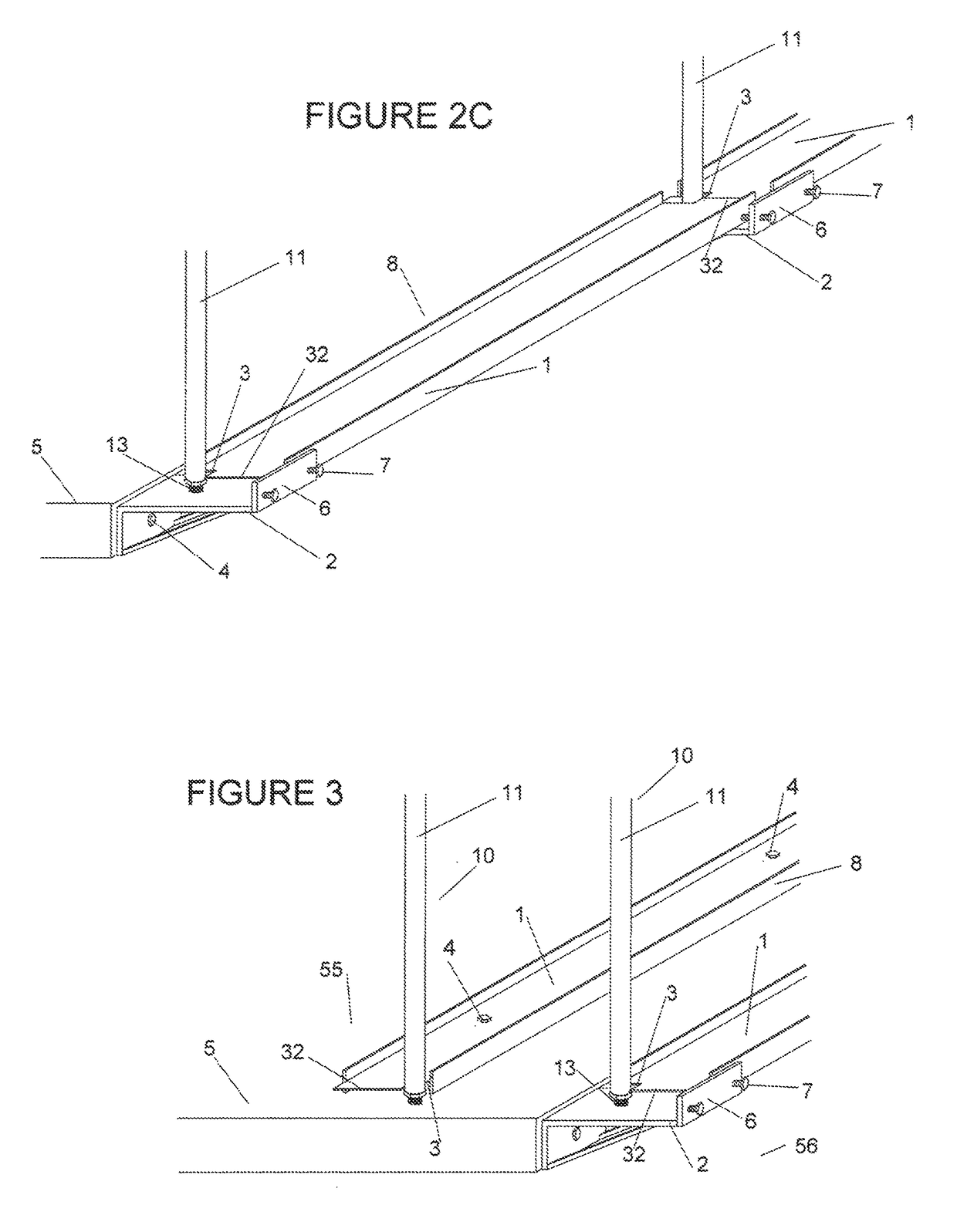
[0049]This invention is a forming system for one or both sides of a two sided, concrete form used to cast walls, columns and other vertical concrete structures. It combines the ease of erection and load carrying capabilities of scaffolding with a greatly simplified concrete forming system that does not utilize form ties or other internal bracing. The forming system includes scaffold frames as the form's vertical support and walers as the form's horizontal support.
[0050]When freshly mixed concrete exerts hydrostatic pressure on the forms it pushes the forms outward and therefore the forms must be braced against such pressure. The forms are braced by horizontal walers which in turn are braced by vertical scaffold frames which are also braced. The scaffold frames act like vertical trusses spanning from the top to the bottom of the wall being cast. The walers provide horizontal support by spanning from scaffold frame to scaffold frame and thereby transferring any lateral load to the sca...
PUM
Abstract
A concrete forming system combining the ease of erection and load carrying capabilities of scaffolding with a simplified erection system. Scaffold frames provide the vertical support and walers, supported by and spanning from scaffold frame to scaffold frame, provide the horizontal support. The wet concrete's hydrostatic pressure is placed on the walers, which transfer the load to the scaffold frames that act like trusses. The scaffold frames have at least two legs and are secured at their bottom to perform as a cantilever or, when the hydrostatic pressure is greater, they are secured at their bottoms and tops to perform as a truss fixed at both ends. As such, this forming system does not use form ties which results in an obstacle free form face and facilitates forms that simply hang from the walers.
Description
RELATED APPLICATIONS[0001]This application claims the benefit of the filing date of U.S. Provisional Application No. 61 / 852,433 filed Mar. 15, 2013 and incorporated herein by reference. This application claims the benefit of copending application Ser. No. 13 / 374,839 filed Jan. 17, 2012 claiming the benefit of the filing date of provisional application Nos. 61 / 461,437 filed Jan. 18, 2011 and 61 / 462,463 filed Feb. 3, 2011. All the above cited applications are incorporated herein by reference.BACKGROUND OF THE INVENTIONPrior Art[0002]The following is a tabulation of some prior art that presently appears relevant:[0003]U.S. PatentsPatent NumberKind CodeIssue DatePatentee2,964,2941960 Dec. 13Imonetti3,584,8271971 Jun. 15Shoemaker3,712,5761973 Jan. 23Dagiel3,874,6271975 Apr. 1Vaught3,945,6021976 Mar. 23Doubleday et al4,640,4911987 Feb. 3Grist et al5,233,8071993 Aug. 10Spera5,562,8451996 Oct. 8Miller et al6,322,047B12001 Nov. 27Holmboe, Jr.7,066,440B22006 Jun. 27Titcomb et al7,530,545B2200...
Claims
Application Information
Patent Timeline
Application Date:The date an application was filed.
Publication Date:The date a patent or application was officially published.
First Publication Date:The earliest publication date of a patent with the same application number.
Issue Date:Publication date of the patent grant document.
PCT Entry Date:The Entry date of PCT National Phase.
Estimated Expiry Date:The statutory expiry date of a patent right according to the Patent Law, and it is the longest term of protection that the patent right can achieve without the termination of the patent right due to other reasons(Term extension factor has been taken into account ).
Invalid Date:Actual expiry date is based on effective date or publication date of legal transaction data of invalid patent.

