Printing apparatus

a technology of printing apparatus and printing plate, which is applied in the direction of typewriters, printing, spacing mechanisms, etc., can solve the problems of inability to handle, the service life estimation described above may not function in some cases appropriately, and the detection sensitivity of position or displacement gradually degrades, so as to achieve more accurate service life management

Active Publication Date: 2017-09-19
SEIKO EPSON CORP
View PDF9 Cites 4 Cited by
  • Summary
  • Abstract
  • Description
  • Claims
  • Application Information

AI Technical Summary

Benefits of technology

[0007]An advantage of some aspects of the invention is to provide a technique that can appropriately perform service life management of a detection means that detects displacement of a discharge head in a printing apparatus that performs printing on a print medium by causing a discharge head to perform scanning movement.
[0012]In this case, for example, a setting history holding unit that holds information related to a history of a print setting and an evaluation unit that evaluates a correlation between the print setting and the stain based on the information held by the signal history holding unit and the information held by the setting history holding unit may be further provided. The amount of generation of the mist of ink from the discharge head varies depending also on the print setting, so that it is possible to realize more accurate service life management by obtaining a correlation between the print setting and the progress of stain.
[0013]Further, for example, a notification unit that notifies a user of a print setting that is evaluated to be highly correlated with the stain by the evaluation unit may be provided. According to such a configuration, it is possible to cause a user to notice that a setting is selected which easily generates stain and shortens the service life of the signal output unit.
[0014]Further, for example, the notification unit may be configured to notify a user of a print setting whose correlation with the stain is lower than that of the current print setting. According to such a configuration, it is possible to guide a user in printing in a print setting where stain is more difficult to occur and prevent the stain from progressing.
[0015]Further, for example, an estimation unit that estimates a service life of the signal output unit in printing based on one print setting, based on an evaluation result of the evaluation unit may be provided. When a correlation between the stain and each print setting is known, it is possible to calculate a progress status of the stain to some extent when a print setting is continuously used and it is also possible to estimate the service life of the signal output unit when the same print setting is continuously used. When service life estimation is performed in this way, timing of cleaning and part replacement is known in advance, so that convenience of a user is improved.
[0018]Further, for example, the printing apparatus may include a support unit that supports the print medium to face the discharge head, a setting of a gap between the support unit and the discharge head can be changed, and the information held by the setting history holding unit may include information related to the gap between the support unit and the discharge head. As the gap between the support unit and the discharge head becomes large, the amount of generation of the mist becomes large, so that the gap becomes information that indicates the degree of progress of the stain. Therefore, it is possible to perform more accurate service life management of the signal output unit by storing the gap between the support unit and the discharge head as information related to the print setting.

Problems solved by technology

In such a printing apparatus, there is a problem that a detection sensitivity of position or displacement gradually degrades due to adhesion of ink mist flying from a discharge head.
A use mode of the printing apparatus as described above varies depending on each user, so that the service life estimation described above may not function appropriately in some cases.
In the related art described above, it is not possible to handle such a problem and it is difficult to appropriately perform the service life management of the detection means.
According to such a configuration, it is possible to cause a user to notice that a setting is selected which easily generates stain and shortens the service life of the signal output unit.
As the stain of the signal output unit progresses, the displacement detection in the displacement detection unit cannot be appropriately performed.

Method used


Image

  • Printing apparatus
  • Printing apparatus
  • Printing apparatus

Examples


Embodiment Construction

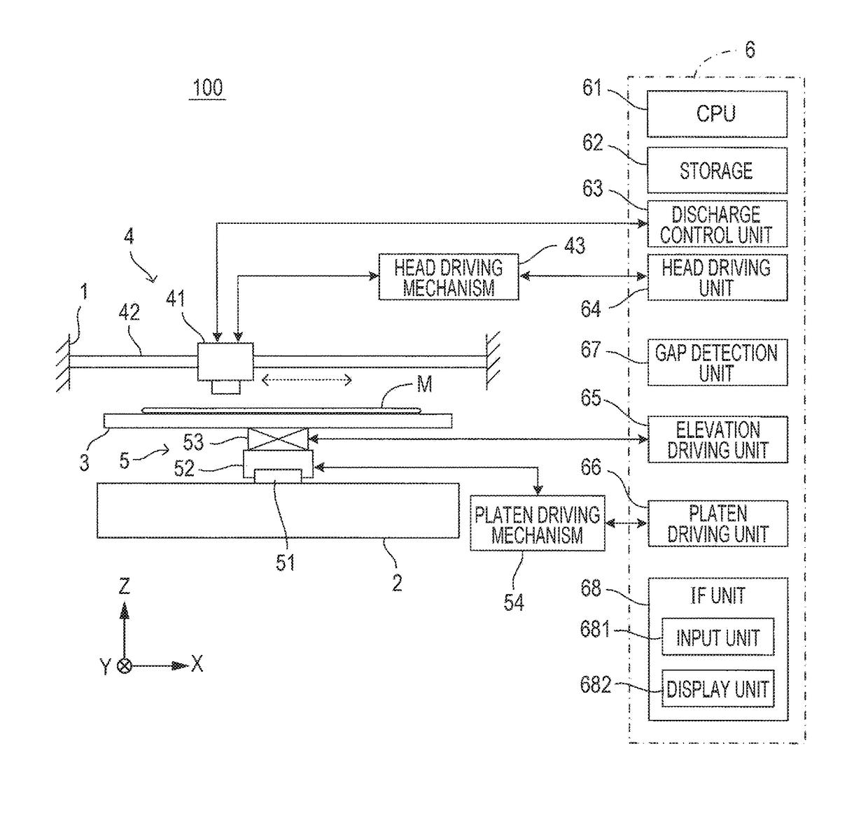
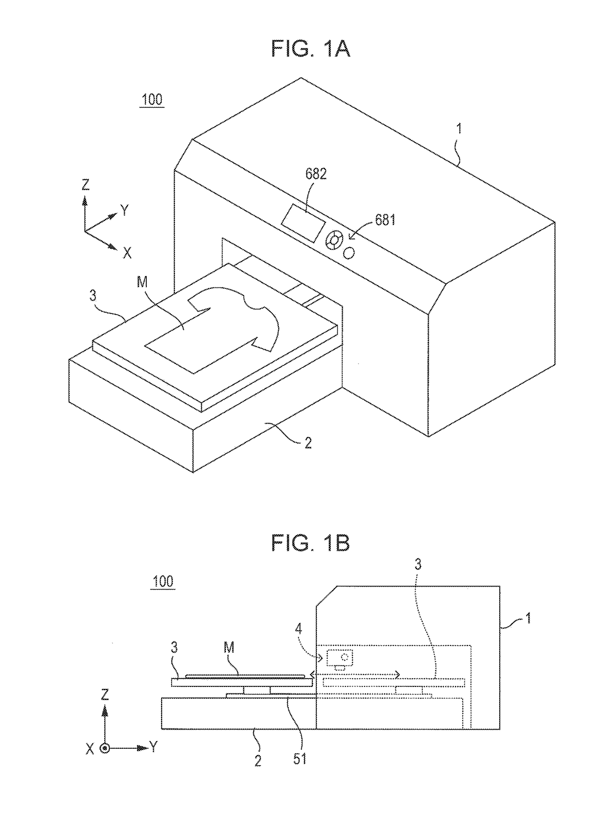
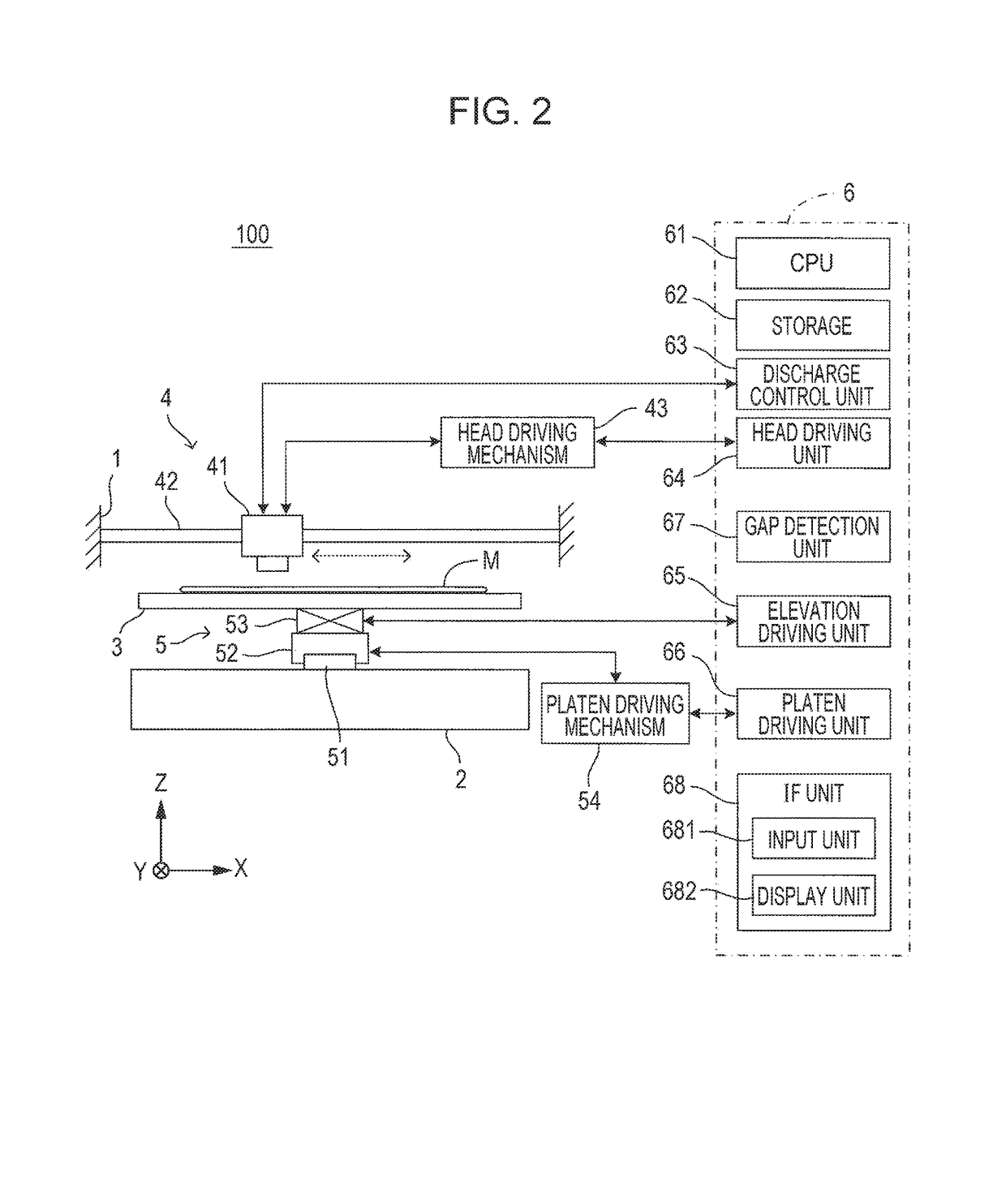
[0028]FIGS. 1A and 1B are diagrams showing a printing apparatus that is an embodiment of a printing apparatus of the invention. More specifically, FIG. 1A is an external perspective view of the printing apparatus 100 and FIG. 1B is a side view showing an internal structure of the printing apparatus 100. FIG. 2 is a diagram showing a main portion of the printing apparatus. The printing apparatus 100 is an apparatus that prints an image on a surface of a print medium M mounted on a platen by an ink jet method. For example, a textile such as a T-shirt is envisaged as the print medium M. However, the print medium M is not limited to textiles. In the drawings described below, to show directions in a uniform manner, an XYZ rectangular coordinate system is set as shown in FIG. 1A. Here, the XY plane represents a horizontal plane and the Z direction represents an upward vertical direction.

[0029]The printing apparatus 100 includes an apparatus main body 1 and a support base 2 protruding in a...


PUM


Abstract

A printing apparatus including a discharge head that performs scanning movement with respect to a print medium and discharges ink to a surface of the print medium, a signal output unit which includes a reference scale in which optical density changes stepwise along a scanning movement direction of the discharge head and a reading unit that optically reads the reference scale and outputs a signal according to the optical density and in which the reference scale and the reading unit move relatively with each other along with the movement of the discharge head, and a stain detection unit that detects stain of the signal output unit based on a detection result of a strength level of the signal.

Description

BACKGROUND[0001]1. Technical Field[0002]The present invention relates to a printing apparatus that performs printing on a print medium by causing a discharge head to perform scanning movement and, in particular to, a technique that optically detects displacement of a discharge head.[0003]2. Related Art[0004]For example, in a printing apparatus such as an ink jet printer that performs printing on a print medium by discharging ink from a discharge head that performs scanning movement with respect to the print medium, an optical detection means may be used to detect displacement of the discharge head. For example, in a technique described in JP-A-2010-188532 (for example, FIG. 3), a displacement of a carriage is detected by a linear encoder in which a scale fixed to a printing apparatus and an optical sensor attached to a carriage are combined. In such a printing apparatus, there is a problem that a detection sensitivity of position or displacement gradually degrades due to adhesion of...

Claims


Application Information

Patent Timeline
Patent Type & Authority Patents(United States)
IPC IPC(8): B41J2/045B41J2/125B41J19/20B41J3/407B41J11/00
CPCB41J2/04586B41J2/125B41J3/4078B41J11/0095B41J19/207B41J29/38
Inventor KIMOTO, YOSHIYUKI
Owner SEIKO EPSON CORP
Why Eureka
Try Eureka