Door handle with light unit

a technology of light unit and door handle, applied in the field of door handle, can solve the problems of difficulty in correctly recognizing objects or feeling dazzling

Active Publication Date: 2017-09-19
KOITO MFG CO LTD +2
View PDF13 Cites 5 Cited by
  • Summary
  • Abstract
  • Description
  • Claims
  • Application Information

AI Technical Summary

Benefits of technology

[0010]The invention provides a door handle in which light emitted from a light emission element is made less visible directly to people around the door handle, thereby reducing inconvenience caused by the direct view.
[0012]According to the configuration, the light emission surface of the light guiding lens is positioned inside the casing. As a result, light emitted from the light emission element becomes less visible directly to people around the door handle, and inconvenience caused by the direct view is reduced.
[0016]According to the configuration, light is radiated in a direction away from a door panel easily.
[0018]According to the configuration, light is radiated to outside of the vehicle easily.

Problems solved by technology

The people who see the light directly may feel dazzling or have difficulty in recognizing objects correctly.

Method used


Image

  • Door handle with light unit
  • Door handle with light unit
  • Door handle with light unit

Examples


Embodiment Construction

[0028]Hereinafter, an embodiment of a door handle according to the invention is explained with reference to the drawings.

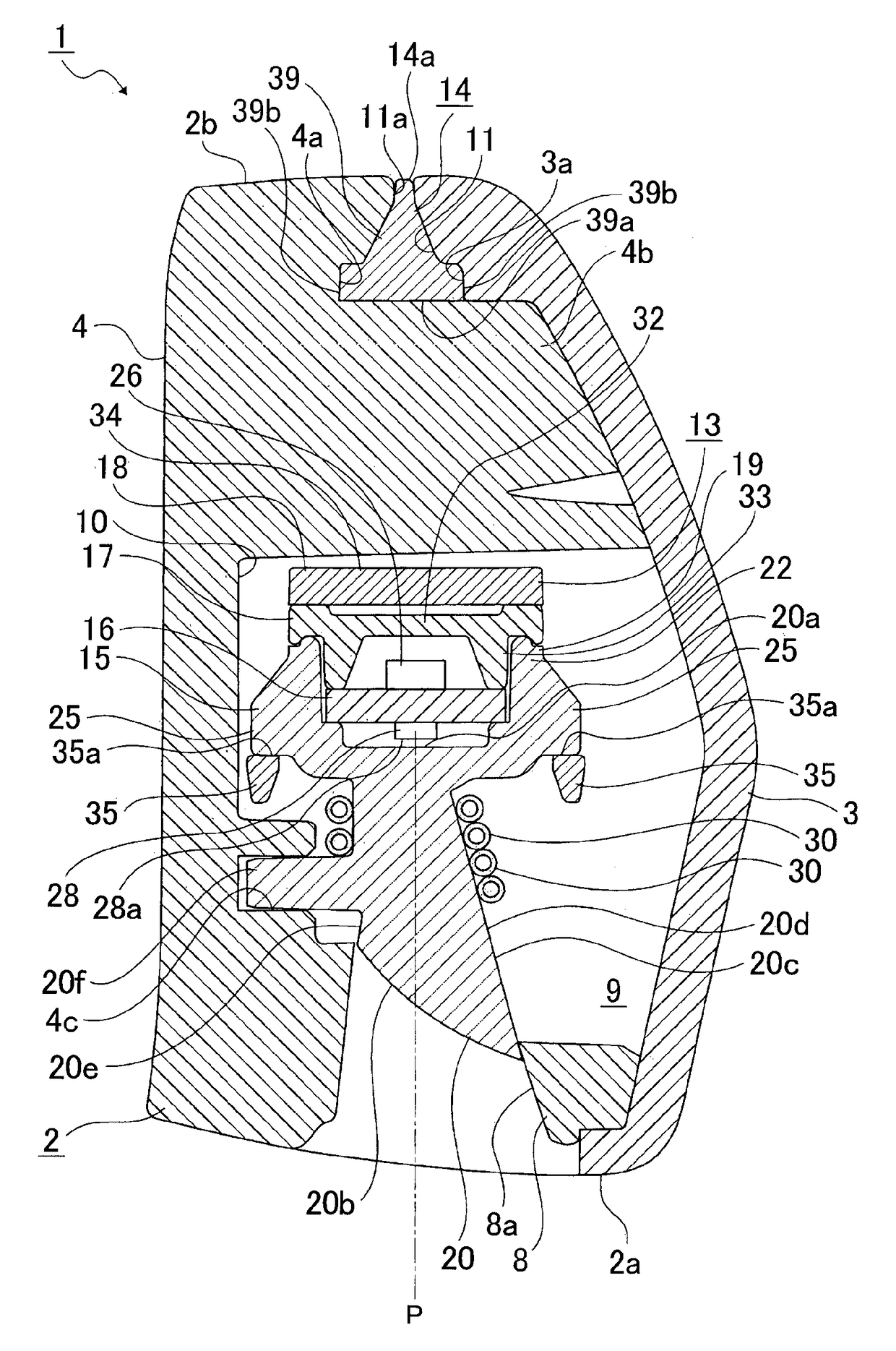
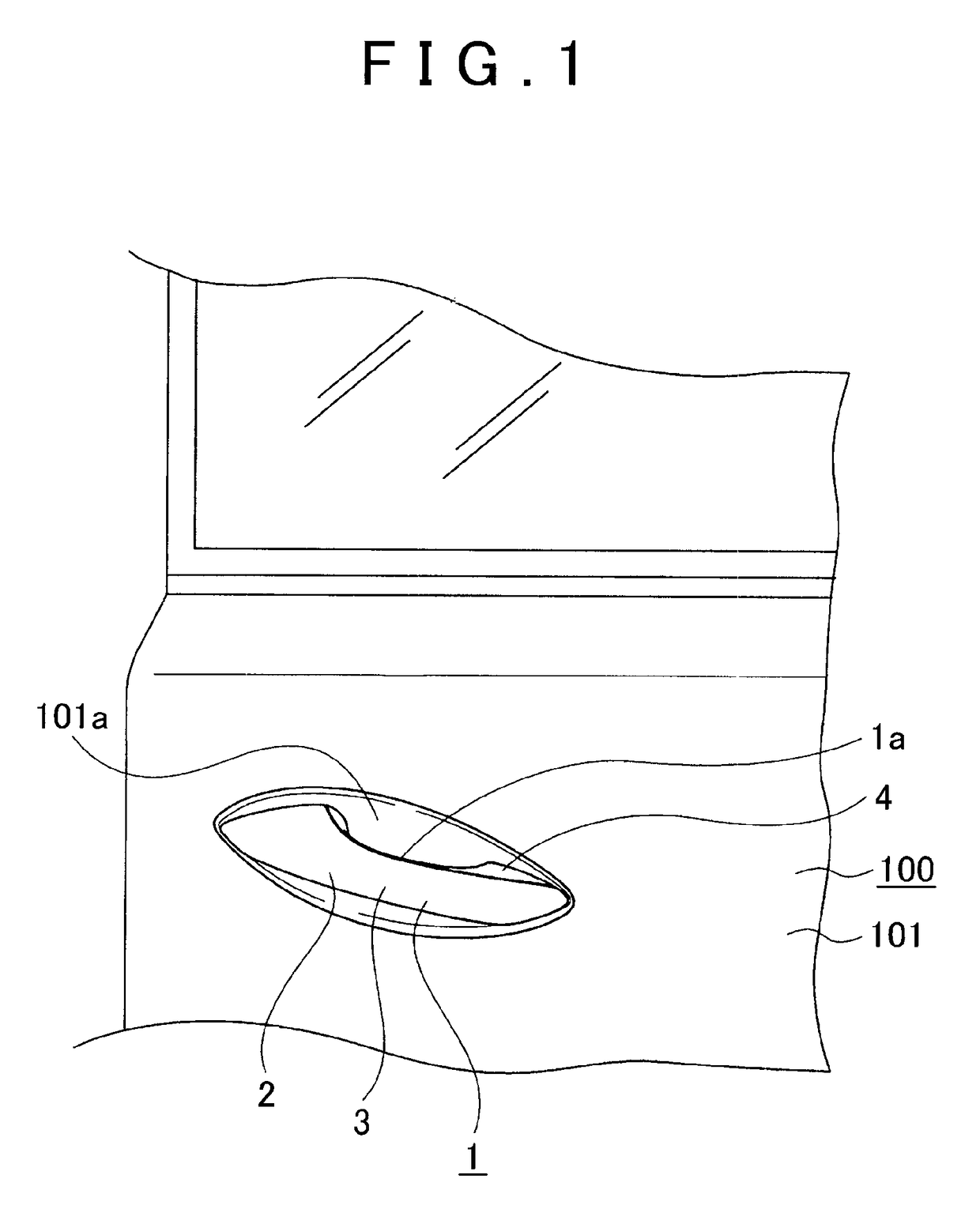
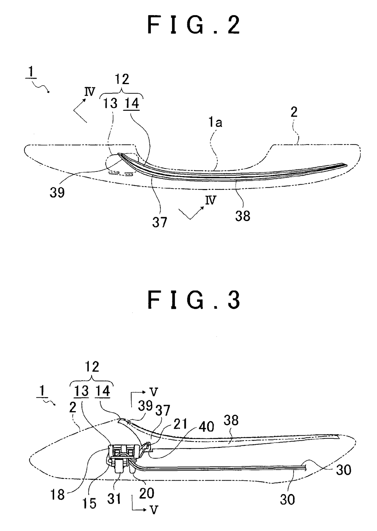
[0029]The door handle 1 has a shape extending in a front-rear direction of the vehicle, for example, and includes a casing 2 and a lamp unit 12 disposed inside the casing 2, which will be described later (FIGS. 1 to 3). A door handle 1 is used as a handle provided for a door 100 of a vehicle. A joint portion of the door handle 1, which is provided at a front end portion thereof and not shown in the drawings, is joined to a door panel 101 (FIG. 1). A panel concavity 101a is formed in an outer surface of the door panel 101. The panel concavity 101a accommodates user's (occupant's) fingers put in an inner side of the door handle 1.

[0030]The door handle 1 pivots about the front end portion such that a rear end portion thereof moves in a right-left direction of the vehicle. When the door 100 is opened, the door handle 1 is caused to pivot by the user's operation in a d...


PUM


Abstract

A door handle includes a casing inside which an accommodation space is provided, and a lamp unit disposed in the accommodation space. The lamp unit includes a light emission element, a circuit board on which the light emission element is mounted, a housing that supports the circuit board, and a light guiding lens that guides light emitted from the light emission element in a predetermined direction. The light guiding lens includes an incident surface that receives light emitted from the light emission element, and an emission surface that emits the light entering in the light guiding lens through the incident surface and is positioned below the incident surface. In the door handle, the emission surface is positioned above a lower surface of the casing.

Description

CROSS REFERENCE TO RELATED APPLICATIONS[0001]This application is a National Stage of International Application No. PCT / IB2014 / 002494 filed Nov. 19, 2014 claiming priority based on Japanese Patent Application No. 2013-238816 filed Nov. 19, 2013, the contents of all of which are incorporated herein by reference in their entirety.BACKGROUND OF THE INVENTION[0002]1. Field of the Invention[0003]The invention relates to a door handle including a lamp unit in which a light guiding lens guides light in a predetermined direction.[0004]2. Description of Related Art[0005]In some door handles, a circuit board is supported by a housing, a light emission element that functions as a light source is mounted on the circuit board, and light emitted from the light emission element is radiated in a predetermined direction (for example, see Japanese Patent Application Publication 2010-229797 (JP-A-2010-229797), Japanese Patent Application Publication 2009-133133 (JP-A-2009-133133), and Japanese Patent A...

Claims


Application Information

Patent Timeline
Patent Type & Authority Patents(United States)
IPC IPC(8): B60Q1/26E05B85/10E05B17/10E05B85/16
CPCB60Q1/2669E05B17/10E05B85/10E05B85/16B60Q2400/40
Inventor TAKAHASHI, HARUHITOKAZAOKA, SHIGEHIKOTATEISHI, MASASHIYOSHINO, MASAKIISHIKAWA, YOSHIKI
Owner KOITO MFG CO LTD
Why Eureka
Try Eureka