Fluid directional apparatus

a technology of directional apparatus and sand bag, which is applied in the direction of mechanical apparatus, water-power plants, machines/engines, etc., can solve the problems of inability to harness the energy of flood surge, inconvenient installation of sand bags, and inability to carry, etc., to achieve a taller and stronger barrier, strengthen the barrier against flood water or storm surge, and enhance the portability

Active Publication Date: 2017-09-19
GRAVITY WELLS TECH
View PDF2 Cites 0 Cited by
  • Summary
  • Abstract
  • Description
  • Claims
  • Application Information

AI Technical Summary

Benefits of technology

[0004]The present invention provides a fluid directional apparatus that meets the stated needs above. An aspect of an embodiment of the present invention contemplates that use of light materials in the construction of the fluid directional apparatus to enhance its portability. In one aspect of an embodiment of the present invention, the apparatus may be made out of plastic. The shape of the apparatus is that of an equilateral triangular prism. This shape allows the container or apparatus to provide a taller and stronger barrier than is possible using sand bags. In addition, modules of the fluid directional apparatus may be stacked together to provide a reinforced barrier against flood water or storm surges. The shape of the fluid directional apparatus also serves to dampen the surge impact force. The apparatus or device as contemplated by the present invention, may be rapidly deployed and may be filled with fluid at the deployment site at a much faster rate than filling sand bags with sand.
[0005]The apparatus contemplated by the invention provides advantages over other flood control systems / devices as it may be easily deployed, is portable and may be filled with liquid or water on location much faster than filling sand bags with sand. In addition, modules of the apparatus may protect much greater areas than would have been covered or protected by sand bag arrangements.

Problems solved by technology

However, deployment of sand bags takes up considerable time and labor as the bags have to be transported to the deployment site and then manually filled with sand.
In addition, filled sand bags do not tend to be easily portable and, while functioning solely as a protective device, they fail to harness the energy of a flood's surge.

Method used


Image

  • Fluid directional apparatus
  • Fluid directional apparatus
  • Fluid directional apparatus

Examples


Embodiment Construction

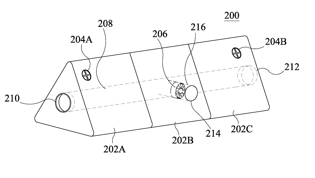
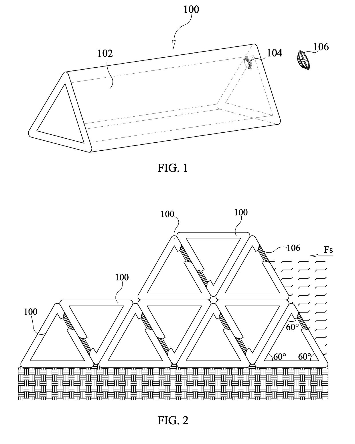
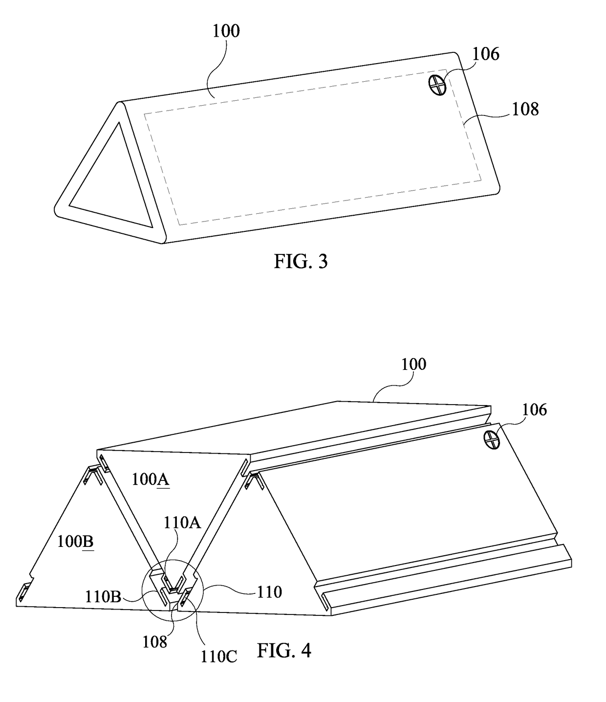
[0030]Referring now to FIG. 1 a perspective view of a fluid directional apparatus 100 according to an aspect of an embodiment of the present invention is shown. Fluid directional apparatus 100 has protective covering 102 meant to protect apparatus 100 from damage by flood debris. Apparatus 100 may be filled with fluid, liquid or semi-liquid material by way opening 104 located on its surface. It should be noted that apparatus 100 may have additional openings 104 both for filling and draining apparatus 100 of fluid, liquid or semi-liquid material. The fluid is used to provide apparatus 100 with weight and support against an oncoming flood surge. The fluid, liquid or semi-liquid material used may also provide apparatus 100 with stability. Each opening 104 may be closed using a corresponding seal tight apparatus 106. In one aspect of an embodiment of the present invention, a screw plug may be used. Seal tight apparatus(es) 106 may be screwed into place to a final position which is flush...


PUM


Abstract

The present invention features a flood damage prevention apparatus having a modular equilateral triangular prism enclosure with an interlocking system used to interlock and position additional modules of the apparatus during flood damage prevention deployment. The interlock system enables additional modules of the flood damage prevention apparatus to be locked in position. Each module may be protected from flood debris damage by way of a protective covering over each enclosure. The apparatus may be filled with fluid via a seal tight opening located on the surface of the enclosure which in turn may be closed using a seal tight apparatus.

Description

CROSS-REFERENCE TO RELATED APPLICATIONS[0001]This Application is a Continuation application of, and claims the benefit of, and is related to, Applicant's following patent application: U.S. Non-Provisional patent application Ser. No. 14 / 224,298 titled “FLUID DIRECTIONAL APPARATUS” filed Mar. 25, 2014, which is incorporated herein in its entirety.FIELD OF THE INVENTION[0002]The present invention relates, in general, to an apparatus used in flood protection, flood water channeling and energy generation.BACKGROUND OF THE INVENTION[0003]Sand bags are normally used to reduce or avoid damage resulting from floods. However, deployment of sand bags takes up considerable time and labor as the bags have to be transported to the deployment site and then manually filled with sand. In addition, filled sand bags do not tend to be easily portable and, while functioning solely as a protective device, they fail to harness the energy of a flood's surge. As such, there is a need for a flood prevention ...

Claims


Application Information

Patent Timeline
Patent Type & Authority Patents(United States)
IPC IPC(8): E02B9/02E02B3/10F03B13/08
CPCE02B3/108F03B13/08F05B2240/40F05B2250/11F05B2250/23F05B2260/30Y02E10/20
Inventor BUTLER, KENT
Owner GRAVITY WELLS TECH
Why Eureka
Try Eureka