
Bracket assembly and systems

a technology of brackets and brackets, applied in the direction of rod connections, dismountable cabinets, mechanical control devices, etc., can solve the problems of inability to adjust the dimensions of the designed structure with prior art systems and brackets, and the inability to assemble prior art brackets together, etc., to achieve quick and efficient erection

Inactive Publication Date: 2017-09-19
POND GARY J
View PDF61 Cites 9 Cited by
  • Summary
  • Abstract
  • Description
  • Claims
  • Application Information

AI Technical Summary

Benefits of technology

Enables efficient and adaptable assembly of support structures, reducing assembly time and allowing for easy adjustment and modular arrangements, suitable for various applications such as storage racks, stages, and decks.

Problems solved by technology

Generally, these structures require many parts and components for assembly, and these structures are not easily adaptable for various modular arrangements.
Likewise, adjustment of the dimensions of the designed structure is not easily carried out with prior art systems and brackets.
In addition, prior art brackets cannot be assembled together before adding beams or fasteners, making many structure assemblies more time-consuming than necessary.

Method used


Image

  • Bracket assembly and systems
  • Bracket assembly and systems
  • Bracket assembly and systems

Examples


Embodiment Construction

[0027]Although the disclosure hereof is detailed and exact to enable those skilled in the art to practice the invention, the physical embodiments herein disclosed merely exemplify the invention which may be embodied in other specific structures. While the preferred embodiment has been described, the details may be changed without departing from the invention, which is defined by the claims.

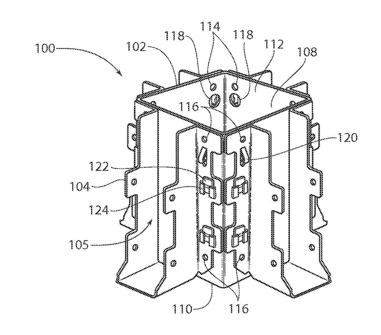
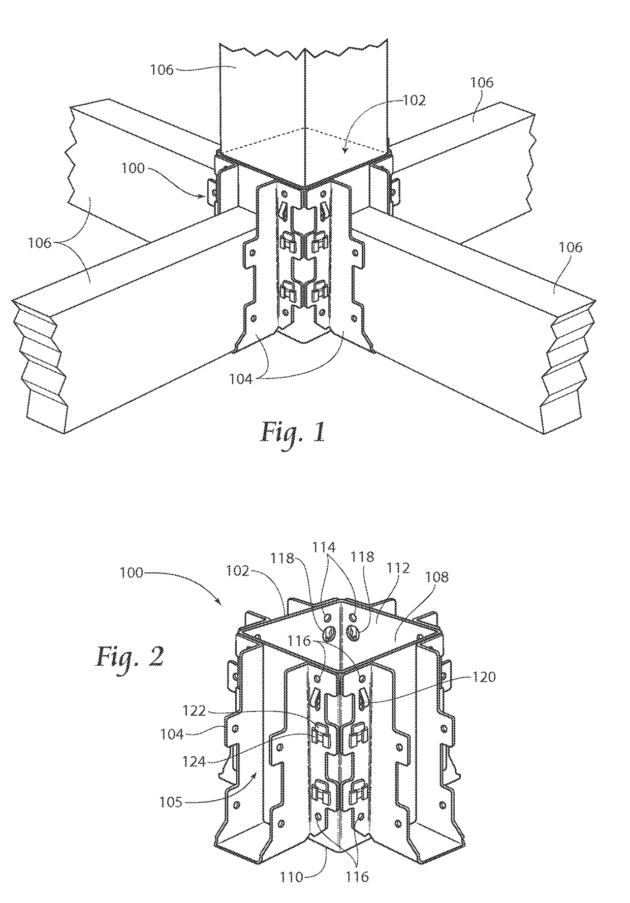
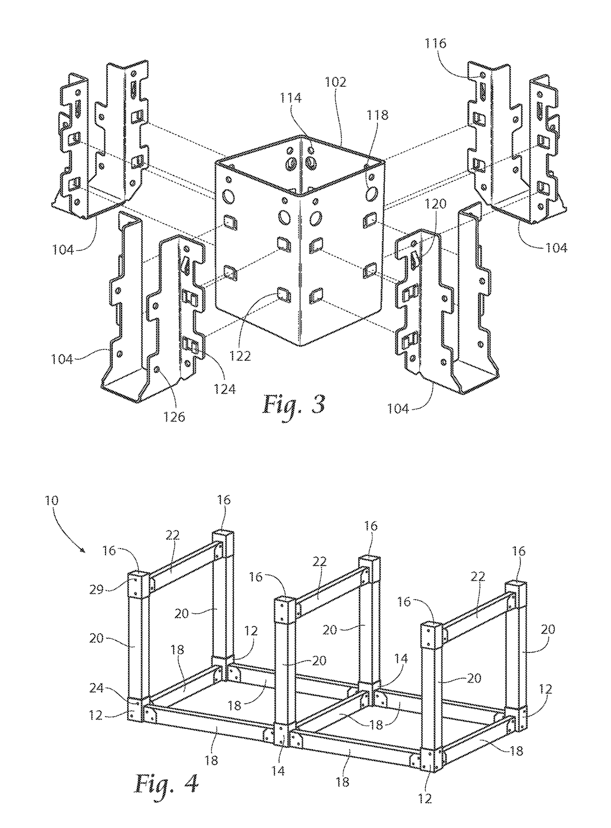
[0028]FIG. 1 depicts a bracket assembly 100 according to the present invention. The bracket assembly 100 generally comprises an internal support sleeve 102 and a plurality of support arms 104 extending from the internal support sleeve 102. Each of the support arms 104 provides support for a support section 106. Depending on the positioning of the bracket assembly 100 when eventually constructing a structure (see, e.g. FIG. 5) the number of support arms 104 will be adapted accordingly. That is, if the bracket assembly 100 is to be used as a corner bracket, e.g. corner bracket 12 in FIG. 5, the inte...


PUM

PropertyMeasurementUnit
structuresaaaaaaaaaa
dimensionsaaaaaaaaaa
sizesaaaaaaaaaa

Abstract

A bracket assembly for use in constructing a support frame. The bracket assembly has an inner support sleeve section and at least one support arm that is attached to the inner sleeve support section, wherein the support arm is attached to the inner support sleeve section without the use of additional fasteners. The invention also is directed towards kits and methods that include the bracket assembly.

Description

RELATED APPLICATIONS[0001]This application claims the benefit of provisional patent application Ser. No. 61 / 607,085 filed Mar. 6, 2012.BACKGROUND OF THE INVENTION[0002]The present invention relates to frames and support structures and more particularly to bracket assemblies used for quick and easy assembly of frame and support structures.[0003]Non-permanent support structures are used in a wide range of settings. For example, these structures can be used as wood storage racks, temporary storage crates, stages and runways, and other structures that may need to be efficiently assembled.[0004]Permanent support structures are used in a wide range of settings. For example, these structures can be used as decks, sheds, lofted beds, and other structures that may need to be efficiently assembled. Prior art structures have been developed but have shortcomings. Generally, these structures require many parts and components for assembly, and these structures are not easily adaptable for various...

Claims


Application Information

Patent Timeline
Patent Type & Authority Patents(United States)
IPC IPC(8): F16B17/00F16B7/18E04B1/26A47B47/00
CPCF16B17/00E04B1/2612F16B7/185A47B47/0016E04B2001/2676Y10T29/4997Y10T29/49826Y10T29/49952Y10T29/49963Y10T403/7039Y10T403/7041E04B1/2608F16B9/052F16B9/058F16B2200/10F16B2200/503
Inventor POND, GARY J.
Owner POND GARY J
Learn More