Directional shovel

a shovel and directional technology, applied in the field of shovels, can solve the problems of limited amount of material that a shovel can displace, damage to a user's joints and muscles, minor or grave and serious injuries, etc., and achieve the effect of more comfortable operation of the shovel

Active Publication Date: 2017-09-26
KHAN SITARA R
View PDF100 Cites 0 Cited by
  • Summary
  • Abstract
  • Description
  • Claims
  • Application Information

AI Technical Summary

Benefits of technology

[0005]It is an object of the invention to provide a directional shovel that is easy and convenient to use.
[0006]It is another object of the invention to provide a shovel that allows a user to easily direct snow or another load without having to lift the shovel to displace the shoveled load.
[0008]The present invention relates to a hand or motorized push shovel / plow with directional left or right side disbursement of snow, granular material, thicker liquids and other such desired materials with ease and comfort. The shovel allows a user to direct a shoveled load to a first or a second side of the shovel while moving the shovel in a substantially straight direction and generally comprises a handle, a shaft extending from the handle to a base shovel blade, a steering mechanism secured along a portion of the shaft or handle and in steering communication with a directional shovel blade that is in a relational arrangement on top of the base shovel blade. The steering plate allows a user to angle the directional blade in a left or right direction. The steering mechanism also allows a user to keep the directional blade in a substantially straight direction. The shovel may further include wheels to reduce the force required to push the shovel. The wheels are preferably of a light weight but sturdy material such as firm plastic, resin, aluminum or other such material or composite of materials that would enable ease of pushing, but not unduly interfere with lifting the shovel to empty it if necessary.
[0011]The shaft / handle adjustment mechanism allows the shaft / handle configuration to be adjusted in height and angle of attachment to the wheels to account for the height and / or comfort of the operator. The base shovel blade adjustment mechanism allows the actual plow angle to the ground be adjusted, to allow for sharper cutting angles while plowing higher or lower levels of snow or other loads. The adjustment mechanisms may employ either screws and turning knobs or levers in combination with grooves or cavities or otherwise to maintain the adjusted positions.
[0013]In the embodiment where the T-Bar is connected to a mini short U-bar, the T-bar is connected to the U-bar close to the wheels and the middle of the T-bar may be connected to the T-bar handle not only to the side near the wheels but also to the middle to the pipe rolling over the rod, thereby connecting the wheels. Further, the U-bar may also have a T-connection wherein a third support is used where the adjustments of the direction of the blade can be controlled. The tube connecting to the T-bar may have on its sides the capability of being adjusted by a flat plate to adjust the level, height and the angle of the arms to the plow. At the wheels and the frame of the rear assembly a plate may be used and is more curved over the wheels. The plate may raise the angle of the plow that is relative to the level of the surface being shoveled by raising the back of the blade (the point furthest from the ground) from facing back toward the operator to the facing the top towards the sky. This adjustment configuration may allow more comfortable operation of the shovel for shoveling loads ranging from light to heavy.

Problems solved by technology

However, the amount of material that a shovel may displace is limited by the surface area of the blade or scoop and height of the load on the blade.
Such an upward force may be damaging to a user's joints and muscles and can result in minor or grave and serious injuries.

Method used


Image

  • Directional shovel
  • Directional shovel
  • Directional shovel

Examples


Embodiment Construction

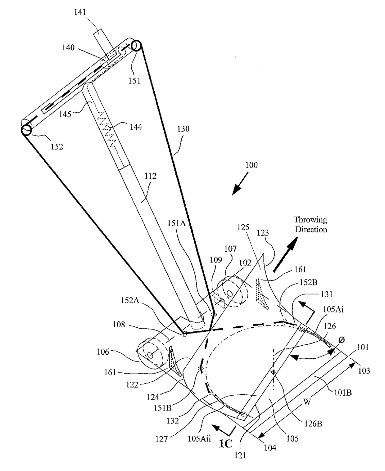
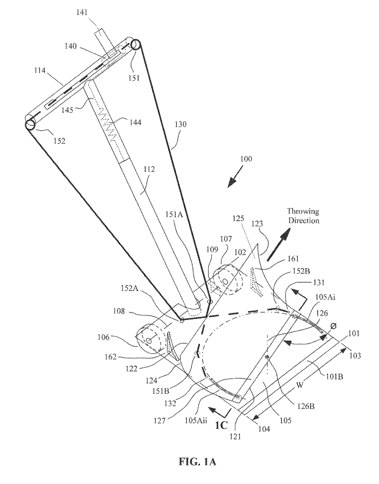
[0035]FIG. 1A shows a first embodiment of the directional shovel 100 of the present invention. The directional shovel 100 may include a base shovel blade 105 that extends from a leading edge 101 to a trailing edge 102, and from a first side 103 to a second side 104. It may be preferable to construct at least a portion of the base shovel blade as a generally flat member, as discussed hereinafter. However, the base shovel blade 105 may also be formed into a modestly curved member.

[0036]The leading edge 101 of the base shovel blade 105 may have a bevel 101B formed on the upper surface. During use of the directional shovel 100, the base shovel blade 105 may normally be disposed to be at an angle with respect to the ground, as the leading edge 101 may be in contact with the ground, while the trailing edge 102 may be elevated above the ground by a one or more wheels attached thereto. Although one wheel may be used to elevate the trailing edge 102, additional stability may be provided thro...


PUM


Abstract

The present invention relates to a hand or motorized push shovel / plow with directional left or right side disbursement of snow, granular material, thicker liquids and other such desired materials with ease and comfort. The shovel allows a user to direct a shoveled load to a first or a second side of the shovel while moving the shovel in a substantially straight direction and generally comprises a handle, a shaft extending from the handle to a base shovel blade, and a steering mechanism secured along a portion of the shaft or handle and in steering communication with a directional shovel blade that is in a relational arrangement on top of the base shovel blade. The steering mechanism allows a user to angle the directional blade in a left or right direction.

Description

CROSS REFERENCE TO RELATED APPLICATIONS[0001]This application claims priority on U.S. Provisional Application Ser. No. 61 / 970,422 filed on Mar. 26, 2014, the disclosures of which are incorporated herein by reference.FIELD OF THE INVENTION[0002]The present invention relates to a shovel that includes a means for directing a shoveled load to a left or right side of the shovel relative to the direction in which the shovel is traveling. In particular, the shovel includes a base blade and a directional blade in a relational arrangement on top of the base blade to direct a shoveled load.BACKGROUND OF THE INVENTION[0003]Many different designs for shovels have been developed over the years. Most existing shovels are comprised of a blade or scoop, either straight or curved, with an edge on the bottom of the blade to help load the material onto the shovel blade. A shaft is connected to the top of shovel blade and may also be connected to a handle at its free end. A shovel is designed to move v...

Claims


Application Information

Patent Timeline
Patent Type & Authority Patents(United States)
IPC IPC(8): E01H5/02E01H5/06E02F3/02E01H5/04
CPCE01H5/061E01H5/02E01H5/045E02F3/02
Inventor KHAN, SITARA R
Owner KHAN SITARA R
Why Eureka
Try Eureka