Backlight, display panel and display device

a display panel and backlight technology, applied in the field of display technology, can solve the problems of not solving the problem, the small size of the display panel is sensitive to brightness mixing, etc., and achieve the effect of wide fluctuation range of brightness, and improved backlight effect of the backligh

Active Publication Date: 2017-09-26
BOE TECH GRP CO LTD +1
View PDF8 Cites 0 Cited by
  • Summary
  • Abstract
  • Description
  • Claims
  • Application Information

AI Technical Summary

Benefits of technology

[0007]In order to solve the above technical problems in the prior art, the present invention provides a backlight, a display panel and a display device. In this backlight, a light mixing structure is disposed on the end surface of the edge of light guide plate, so as to avoid the glowworm phenomenon in the effective back light area of the small-size backlight and hence to improve the back light effect of the backlight. Meanwhile, this configuration can also solve the problem of wide fluctuation range of brightness among various backlights.
[0021]The beneficial effects of the present invention: in the backlight according to the present invention, a light mixing structure is disposed on the end surface of the edge of light guide plate, and is capable of mixing the light having different brightness, which is emitted from the first light sources and the second light sources into light with uniform brightness, so as to avoid the glowworm phenomenon in the effective back light area of the small-size backlight and hence to improve the back light effect of the backlight. Meanwhile, this configuration may reduce the difference of brightness between different backlights and make the brightness of various backlights tend to be uniform, thereby solving the problem of wide fluctuation range of brightness among various backlights.
[0022]The display effect of the display panel according to the present invention can be improved by using the above backlight.
[0023]The display quality of the display device according to the present invention can be improved by using the above display panel.

Problems solved by technology

However, since the back light area in the small-size display panel is relatively small, the small-size display panel is sensitive to brightness mixing.
As a result, the above arrangement of the light source for brightness mixing in the large-size display panel may not solve the problem of wide fluctuation range of brightness among various backlights in the small-size display panel.

Method used


Image

  • Backlight, display panel and display device
  • Backlight, display panel and display device
  • Backlight, display panel and display device

Examples


embodiment 1

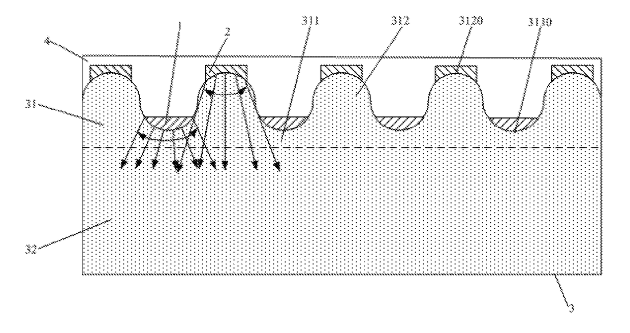
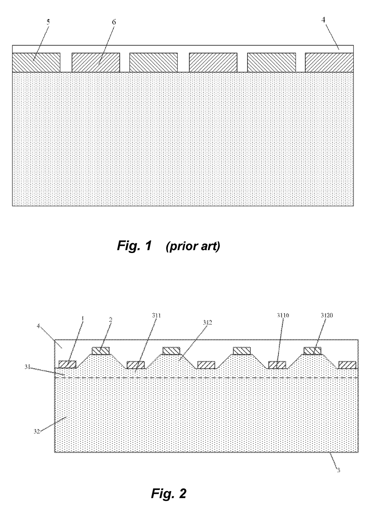
[0031]As shown in FIG. 2, the present embodiment provides a backlight including first light sources 1, second light sources 2 and a light guide plate 3. The first light sources 1 and the second light sources 2 are disposed above the same end surface of an edge of the light guide plate 3. Light-emitting surfaces of the first light sources 1 and the second light sources 2 face the end surface of the edge of the light guide plate 3. The brightness of light emitted from the first light source 1 is different from that of light emitted from the second light source 2. A light mixing structure 31 is disposed on the end surface of the edge of the light guide plate 3, and is capable of mixing the light emitted from the first light source 1 and the light emitted from the second light source 2 into light with uniform brightness.

[0032]Disposing the light mixing structure 31 may avoid the glowworm phenomenon (i.e., a plurality of alternately dark and bright dots appear in an effective back light ...

embodiment 2

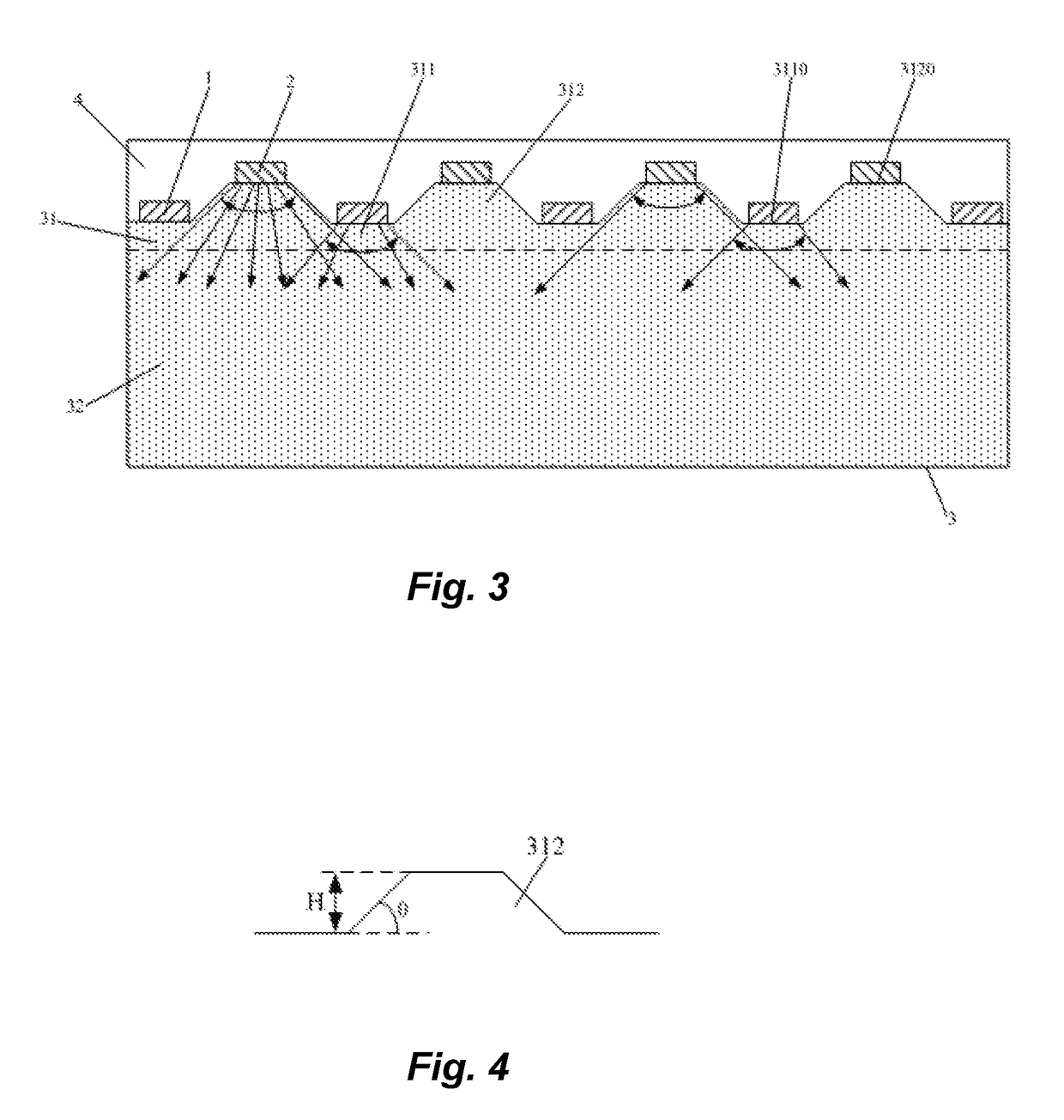
[0040]The present embodiment provides a backlight, as shown in FIG. 5. Unlike Embodiment 1, the shapes of contours of cross sections, which are parallel to the light guide plate 3 and perpendicular to the end surface of the edge of the light guide plate 3, of the concave parts 311 and the convex parts 312 are similar or identical parabolic curves. Opening directions of the parabolic curves are different between the concave parts 311 and the convex parts 312. The light-emitting surface of the first light source 1 is attached to the bottom surface 3110 of the corresponding concave part 311, and the light-emitting surface of the second light source 2 is attached to the top surface 3120 of the corresponding convex part 312.

[0041]The area of the region, in which the light emitted from the first light sources 1 and the second light sources 2 is mixed to have uniform brightness, can be reduced by applying the above configuration, thereby the area of the effective back light region 32 of th...

embodiment 3

[0045]The present embodiment provides a display panel including the backlight according to Embodiment 1 or Embodiment 2.

[0046]The display effect of the display panel can be improved by using the backlight according to Embodiment 1 or Embodiment 2.


PUM


Abstract

The present invention provides a backlight, a display panel and a display device, The backlight includes: a first light source and a second light source, the brightness of light emitted from the first light source is different from that of light emitted from the second light source; and a light guide plate, the first light source and the second light source are disposed above the same end surface of an edge of the light guide plate, and light-emitting surfaces of the first light source and the second light source face the end surface of the edge of the light guide plate, a light mixing structure is disposed on the end surface of the edge of light guide plate and is capable of mixing the light emitted from the first light source and the light emitted from the second light source into light with uniform brightness.

Description

FIELD OF THE INVENTION[0001]The present invention relates to the field of display technology, and in particular, relates to a backlight, a display panel and a display device.BACKGROUND OF THE INVENTION[0002]Liquid crystal display (LCD for short) device, due to its advantages of small size, low power consumption, less radiation, and the like, has become a mainstream product of flat-panel display devices at present. A backlight is an essential component of the liquid crystal display device and is used for providing back light for the display panel in display.[0003]A side type backlight is usually adopted in order to facilitate a tendency of the display panel to be thinner and lighter. In the side type backlight, a light source is generally arranged at an edge of a light guide plate on one side thereof, so that the light emitted from the light source enters the light guide plate from a side surface of the light guide plate edge. The light source in the backlight is usually a LED light ...

Claims


Application Information

Patent Timeline
Patent Type & Authority Patents(United States)
IPC IPC(8): F21V8/00G02B6/00
CPCG02B6/0068G02B6/0021
Inventor CHU, HANQIPARK, JINMOOCHEN, SHOUNIAN
Owner BOE TECH GRP CO LTD
Why Eureka
Try Eureka