
Solar cell and method of fabricating the same

a technology of solar cells and solar cells, applied in the field of solar cells, can solve problems such as electrical loss, and achieve the effects of preventing defects, ensuring reliability, and reducing thermal expansion and thermal contraction

Active Publication Date: 2017-09-26
LG INNOTEK CO LTD
View PDF13 Cites 0 Cited by
  • Summary
  • Abstract
  • Description
  • Claims
  • Application Information

AI Technical Summary

Benefits of technology

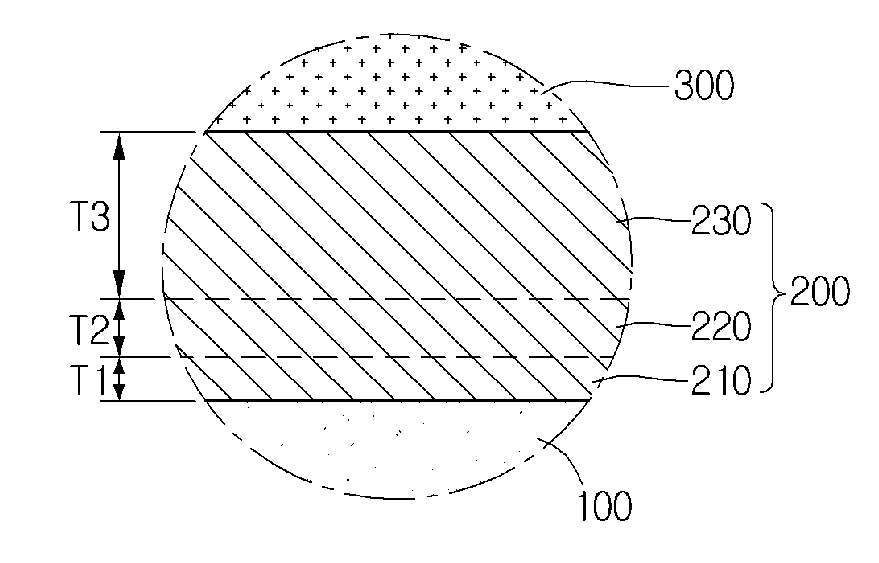
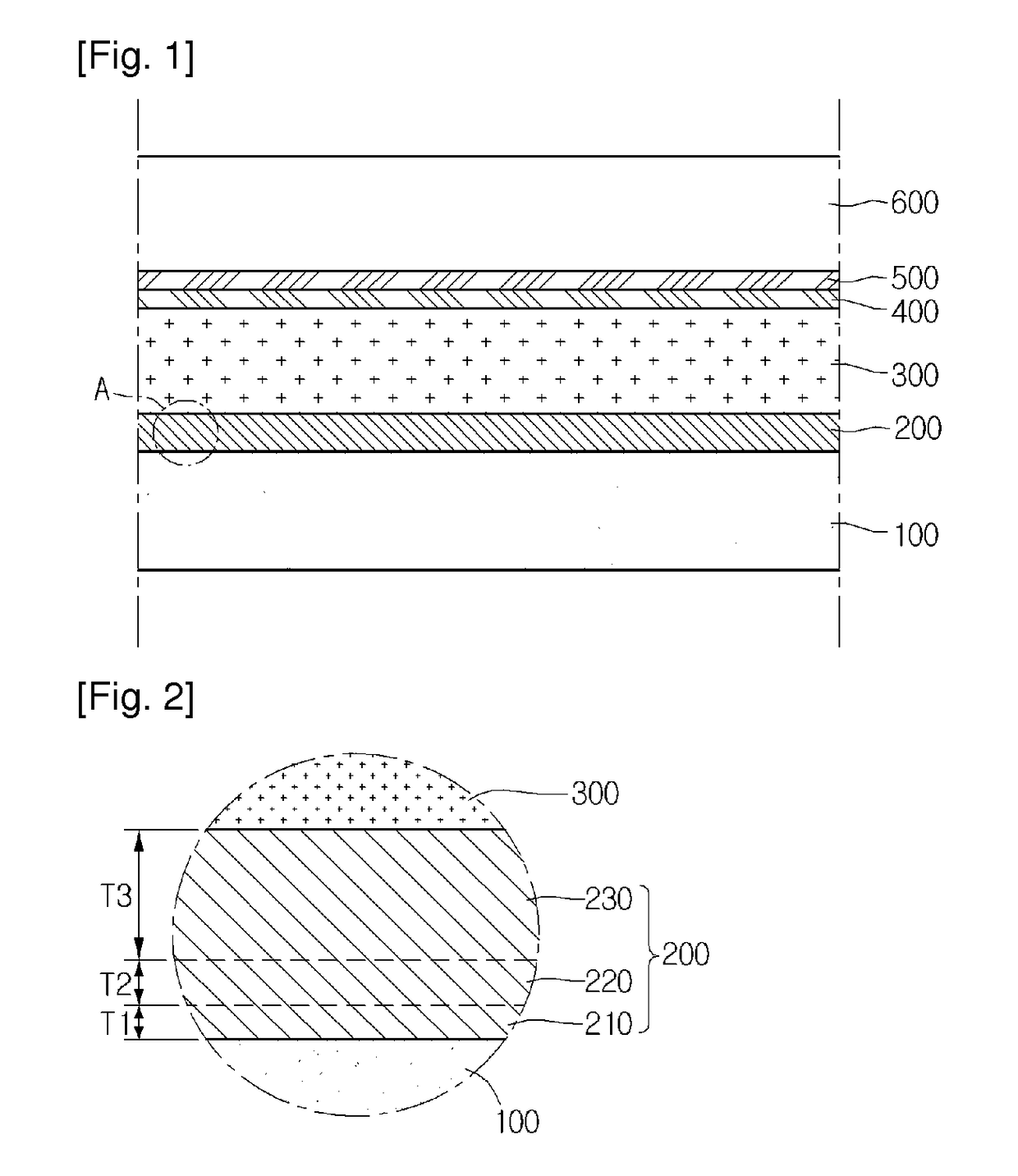
[0015]The solar cell according to the embodiment includes the back electrode layer, and the back electrode layer includes the first to third layers. The first to third layers have different fine structures to mitigate the thermal expansion and thermal contraction according to the layers. In other words, when performing a P1 process with respect to the back electrode layer, the different fine structures of the first to third layers serve as a buffer against the shock wave by the laser. In other words, the thermal contraction is gradually performed in the first to third layers 210 to 230, so that a burr phenomenon or a lift off phenomenon may be prevented. Accordingly, the defects can be prevented from being caused by the laser process of the solar cell. Therefore, the shunt path and the structural short can be prevented after the subsequent process has been performed, so that the reliability can be ensured.

Problems solved by technology

The defects may provide an electrical shunt path or may cause electrical loss, after the subsequent processes have been performed.

Method used


Image

  • Solar cell and method of fabricating the same
  • Solar cell and method of fabricating the same

Examples


Embodiment Construction

[0018]In the description of the embodiments, it will be understood that, when a layer (film), a region, a pattern, or a structure, is referred to as being “on” or “under” another substrate, another layer (film), another region, another pad, or another pattern, it can be “directly” or “indirectly” on the other substrate, the other layer (film), the other region, the other pad, or the other pattern, one or more intervening layers may also be present. Such a position of each layer has been described with reference to the drawings.

[0019]The thickness and size of each layer (film), each region, each pattern, or each structure shown in the drawings may be exaggerated, omitted or schematically drawn for the purpose of convenience or clarity. In addition, the size of each layer (film), each region, each pattern, or each structure does not utterly reflect an actual size.

[0020]Hereinafter, the embodiment of the disclosure will be described in detail with reference to accompanying drawings.

[00...


PUM


Abstract

Disclosed are a solar cell and a method of fabricating the same. The solar cell includes a support substrate, a back electrode layer on the support substrate, a light absorbing layer on the back electrode layer, and a front electrode layer on the light absorbing layer. The back electrode layer includes at least three layers. The method includes forming a first layer on a support substrate, forming a second layer on the first layer, forming a third layer on the second layer, forming a light absorbing layer on the third layer, and forming a front electrode layer on the light absorbing layer.

Description

CROSS-REFERENCE TO RELATED APPLICATIONS[0001]This application is the U.S. national stage application of International Patent Application No. PCT / KR2012 / 009867, filed Nov. 21, 2012, which claims priority to Korean Application No. 10-2011-0121870, filed Nov. 21, 2011, the disclosures of each of which are incorporated herein by reference in their entirety.TECHNICAL FIELD[0002]The embodiment relates to a solar cell and a method of fabricating the same.BACKGROUND ART[0003]A method of fabricating a solar cell for solar light power generation is as follows. First, after preparing a substrate, a back electrode layer is formed on the substrate and patterned by a laser, thereby forming a plurality of back electrodes.[0004]Thereafter, a light absorbing layer, a buffer layer, and a high resistance buffer layer are sequentially formed on the back electrodes. Various schemes, such as a scheme of forming a Cu(In,Ga)Se2 (CIGS) based-light absorbing layer by simultaneously or separately evaporating ...

Claims


Application Information

Patent Timeline
Patent Type & Authority Patents(United States)
IPC IPC(8): H01L31/00H01L31/0224H01L31/0463H01L31/024H01L31/0392
CPCH01L31/022441H01L31/024H01L31/022425H01L31/03923H01L31/0463Y02E10/541H01L31/042H01L31/04H01L31/18
Inventor LEE, DONG KEUN
Owner LG INNOTEK CO LTD
Learn More