
Filter element and housing with cooperating filter media support structures

a technology of supporting structure and filter element, which is applied in the direction of dispersed particle separation, fuel air cleaner, separation process, etc., can solve the problems of pressure drop across the filter element, deformation of the filter element, and unsatisfactory deflection force, so as to strengthen the support grid and strengthen the filter media. the effect of deflection for

Active Publication Date: 2017-10-03
MANN HUMMEL GMBH
View PDF12 Cites 0 Cited by
  • Summary
  • Abstract
  • Description
  • Claims
  • Application Information

AI Technical Summary

Benefits of technology

The invention is an improved air filter assembly or air cleaner that includes an air filter element with at least one filter media. It also includes a peripheral seal frame and a substantially rigid support grid to strengthen the filter media against deflection forces. The support grid includes at least one substantially rigid side rail and at least one support rib to further strengthen the support grid. The support posts and support post receiving members provide support to the filter media and resist deformation of the media. A cushioning member may be added to reduce noise and vibration during operation. The invention helps to improve the performance and durability of the air filter assembly.

Problems solved by technology

This air flow induced pressure drop produces undesirable deflection forces in the filter media of the filter element.
In operation, the filter element is subject to deflection forces induced by airflow through the filter element and the resulting pressure drop across the filter element.
These deflection forces may tend to deform the filter element.
Accumulation of dust or dirt in the filter media tends to obstruct pores in the filter media and increase the pressure drop with an increase resulting deflection forces.
Water wets the filter media, obstructs pores in the media and may act to further obstruct air flow through the media with the resultant further increase in pressure drop and resultant deflection forces.

Method used


Image

  • Filter element and housing with cooperating filter media support structures
  • Filter element and housing with cooperating filter media support structures
  • Filter element and housing with cooperating filter media support structures

Examples


Embodiment Construction

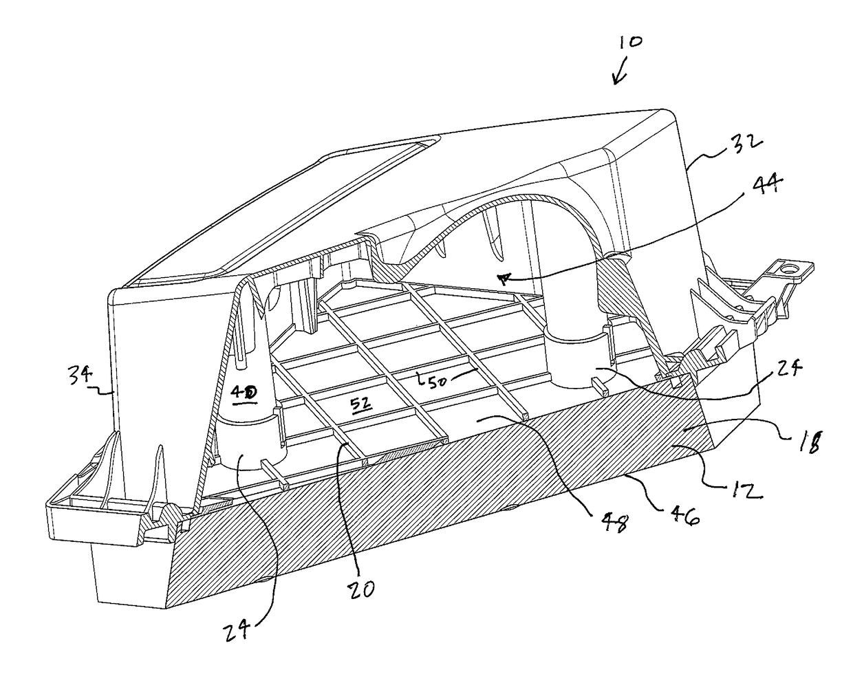
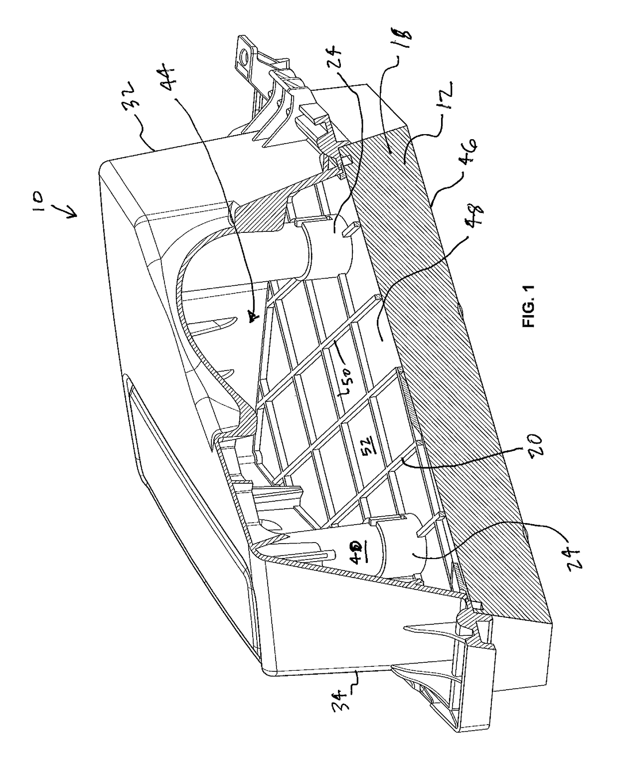
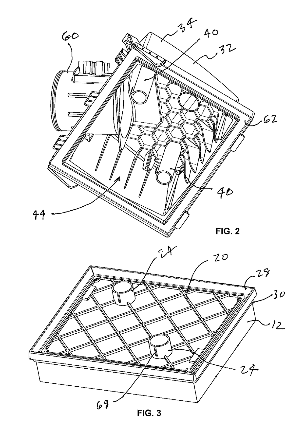
[0030]FIGS. 1-4 depict a preferred embodiment of the filter element support structure, consistent with the disclosed invention. FIG. 1 shows perspective cut-away or section view of the a filter assembly 10 having a filter element 12 installed into and supportively interacting with and a half portion of a filter housing 32 depicting features of a filter media support structure consistent with the present invention.

[0031]The half portion 34 of the filter housing 32 may be a housing cover or a housing base. The half portion 34 of the filter housing 32 is configured to mate with a second half portion of the filter housing (not shown) to enclose an interior chamber 44 into which the filter element 12 is replaceably or exchangeably received. The filter element 12 has an inflow face 46 arranged at a dirty side of the filter element 12 and an axially opposing outflow face 48 arranged at a clean side of the filter element. An axial direction is defined as the direction that the outflow face ...


PUM

PropertyMeasurementUnit
transfer forcesaaaaaaaaaa
elasticaaaaaaaaaa
pressureaaaaaaaaaa

Abstract

A filter element having a filter media support structure as well as a filter assembly having interacting filter media support structure components are disclosed. The support structure includes a support grid arranged on a clean side of the filter media. At least one support member is secured onto the support grid and extends outwardly away from the support grid and the filter media. The at least one support member is configured and adapted to supportively engage a respective mating support member to transfer forces from the filter element to the housing.

Description

CROSS REFERENCE TO RELATED APPLICATIONS[0001]This application claims the benefit of U.S. Provisional Patent Application No. 62 / 041,437 filed Aug. 25, 2014.TECHNICAL FIELD[0002]The present invention relates to vehicle engine air intake systems and air filters for such systems and, more particularly, to air filters provided with media reinforcing elements.BACKGROUND OF THE INVENTION[0003]Internal combustion engines require a source of combustion air. A typical source for combustion air is air drawn from outside of the vehicle, which commonly includes particulate contaminants. An air cleaner including an air filter element is normally provided in the air induction system to capture these particulate contaminants before combustion air is delivered to the vehicle engine.[0004]Air filters include filter media having relatively small pores for air flow that operate to inhibit the passage of undesired particulate contaminants. Since the presence of a filter media in the intake air stream ac...

Claims


Application Information

Patent Timeline
Patent Type & Authority Patents(United States)
IPC IPC(8): B01D46/52B01D46/00F02M35/02B01D46/10
CPCB01D46/0005B01D46/10B01D46/521B01D2265/06
Inventor FEDAK, ERICH
Owner MANN HUMMEL GMBH
Learn More