Flanging press

a technology of flanging press and flanging plate, which is applied in the direction of metal-working holders, supporters, positioning apparatuses, etc., can solve the problem of large installation area, and achieve the effect of simplifying the access to the joining location

Active Publication Date: 2017-10-03
FFT PRODIONSSYST
View PDF14 Cites 69 Cited by
  • Summary
  • Abstract
  • Description
  • Claims
  • Application Information

AI Technical Summary

Benefits of technology

[0008]In accordance with an aspect of the invention, the pressing drive is a fluidic pressing drive comprising a bellows which can be charged with pressure fluid, preferably pressurised gas, and acts on the flanging die unit or flanging bed in the pressing direction when charged with pressure, thus generating the pressing force. The bellows can be arranged on a rear side of the flanging die unit facing away from the flanging bed or on a rear side of the flanging bed facing away from the flanging die. It can extend over the length of the flanging bed, such that the fluid pressure in the interior of the bellows acts on a large area of the bellows. A pressure bellows which is operated using pressurised gas, preferably pressurised air, can therefore also generate a sufficiently large pressing force purely fluidically, such that it can act directly on the flanging bed or flanging die, as is preferred, and in particular be arranged directly on a rear side of the flanging bed or flanging die unit and not need stepping down by a gear system. A pressure bellows which can be operated using pressurised air can be very easily connected to a pressurised air supply which is provided in production plants by their very nature. Conventional pressurised air supplies typically deliver a pressure of for example 6 or 12 bars. It is not necessary to provide a unit especially for the pressing drive.
[0052]The second end-facing wall structure can comprise a surface which faces the component and is adapted to the contour of the component, such that the component, when suctioned, is supported in regions on the second end-facing wall structure. The support region or regions thus obtained can be shaped and arranged as viewed over the area of the component in such a way that the component is prevented from being warped due to the partial vacuum which prevails in the suction chamber.

Problems solved by technology

Such flanging and / or hemming presses require large installation areas which, due to the limited space available in production plants, are often not available or only available at locations which are sub-optimal for production.

Method used


Image

  • Flanging press
  • Flanging press
  • Flanging press

Examples


Embodiment Construction

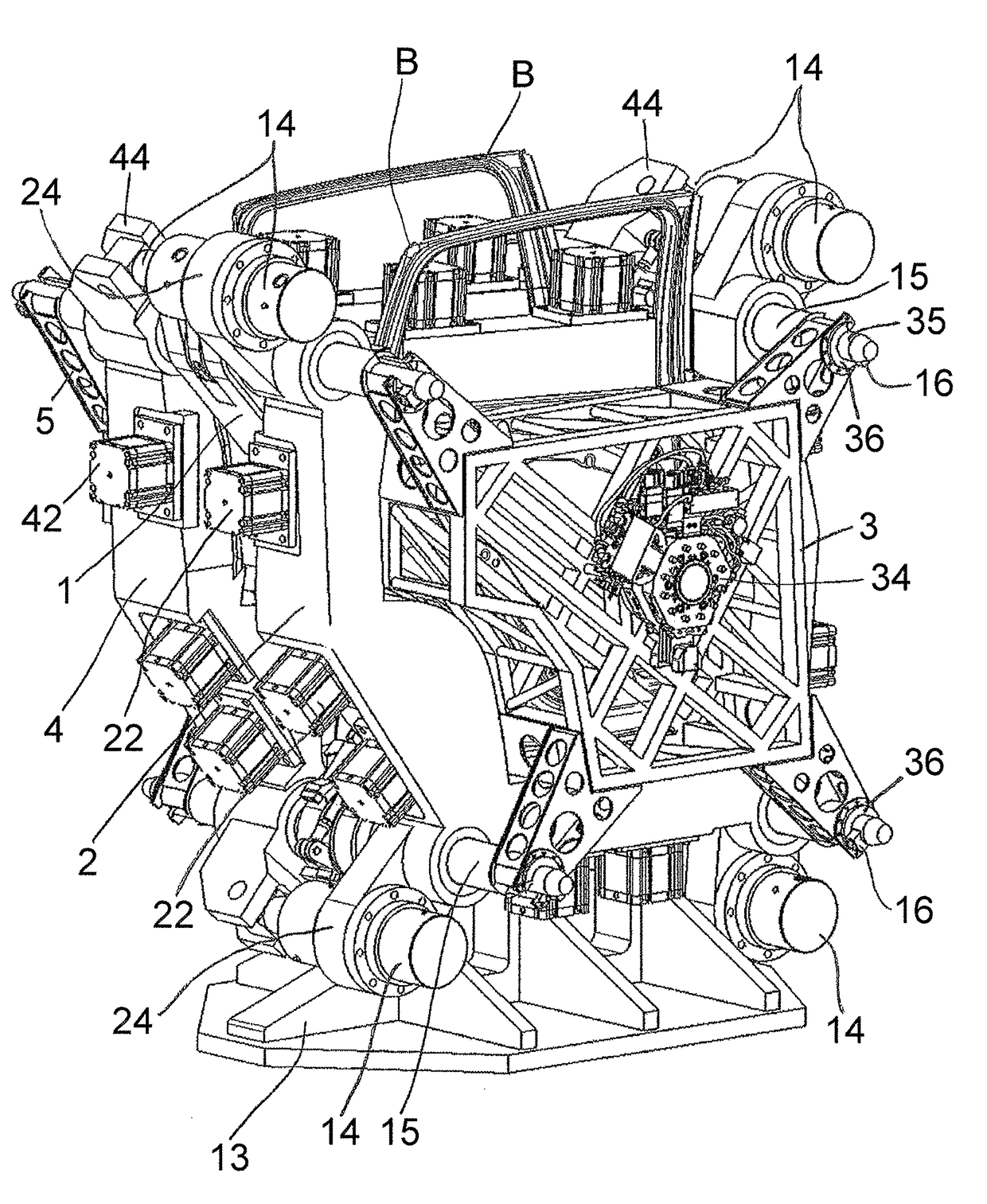
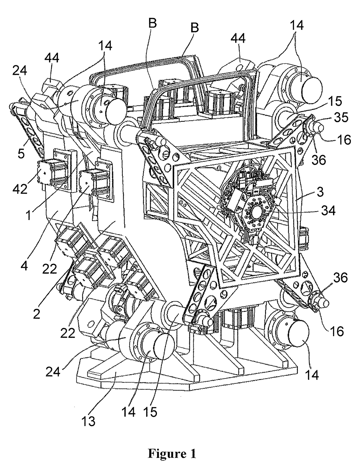
[0111]FIG. 1 shows a flanging press of a first example embodiment. The flanging press is embodied as a dual press, i.e. it comprises a first flanging press and a second flanging press which are arranged next to each other in a sandwich arrangement, back-to-back and upright. The press is arranged in a stationary manner in the production plant.

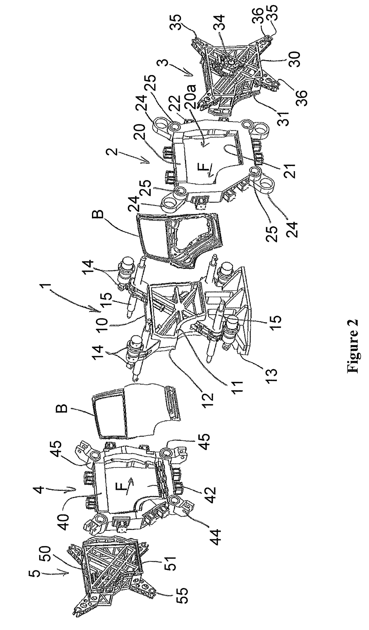
[0112]FIG. 2 shows the flanging press separated into its main components, wherein the main components are lined up parallel to a pressing direction F. Said main components include a base structure 1 which is centrally arranged in relation to the pressing direction F, a first flanging die unit 2 which is arranged to the right of the base structure 1, a first suppressor 3, a second flanging die unit 4 which is arranged to the left of the base structure 1, and a second suppressor 5. Two components B can be simultaneously flanged using the press. The components are for example the left-hand door B and the right-hand door B of a passenger car. In the...


PUM

PropertyMeasurementUnit
pressureaaaaaaaaaa
lengthaaaaaaaaaa
thicknessaaaaaaaaaa

Abstract

Flanging press for folding over a flange of a component, preferably of a vehicle part, the press being arranged in a stationary manner and including at least the following: (a) a basic structure with a flanging bed, against which the component can be pressed in a pressing direction in order for the flange to be folded over, (b) a flanging die unit with a flanging die for folding over the flange, (c) and a pressing drive for generating a pressing force which acts on the component in order for the flange to be folded over, (d) wherein the flanging die and the flanging bed can be moved relative to one another in the pressing direction by the pressing drive in order for the pressing force to be exerted, characterized in that (e) the pressing drive includes a bellows which can be subjected to the action of pressurized fluid, preferably compressed gas, and, under the action of pressure, acts on the flanging die unit or the flanging bed in the pressing direction and thus generates at least some of the pressing force, and the bellows has a bellows surface which extends transversely to the pressing direction and can be subjected to the action of the pressurized fluid.

Description

CROSS REFERENCE TO RELATED APPLICATIONS[0001]This application is the U.S. National Phase Application of PCT / EP2013 / 065932, filed Jul. 29, 2013, which claims priority to European Patent Application No. 12178365.8, filed Jul. 27, 2012 and German Patent Application No. 20 2013 002 810.6, filed Mar. 25, 2013, the contents of such applications being incorporated by reference herein.FIELD OF THE INVENTION[0002]The invention relates to a flanging press for folding over a flange of a component, preferably a vehicle part such as for example a vehicle door. It can in particular be a flanging press for manufacturing a hemmed connection. In such applications, the flanging press is a hemming press. In principle, however, it can also be used to fold over a flange completely or only partially or to perform a joining process. It is preferably used in the series production of vehicle parts.BACKGROUND OF THE INVENTION[0003]DE 10 2009 059 676 A1, which is incorporated by reference, discloses a flangin...

Claims


Application Information

Patent Timeline
Patent Type & Authority Patents(United States)
IPC IPC(8): B21D39/02B23Q3/08
CPCB21D39/021B23Q3/088
Inventor SCHAAFHAUSEN, WILFRIEDGROHMANN, JURGENMOTZKAU, GUNTERZIEGLER, FELIX
Owner FFT PRODIONSSYST
Why Eureka
Try Eureka