Hinged glass handrail sill

a technology of glass handrails and hinges, which is applied in the field of hinged glass handrail sills, mounting systems, etc., can solve the problems of difficult installation of glass handrail systems, difficult alignment of individual panels, and often required substantial labor, so as to facilitate identification of the correct wedges and less force

Active Publication Date: 2017-10-03
SOLAR INNOVATIONS LLC
View PDF24 Cites 18 Cited by
  • Summary
  • Abstract
  • Description
  • Claims
  • Application Information

AI Technical Summary

Benefits of technology

[0009]In embodiments that adjust the sill plate exclusively by using an adjustment screw, the inventor has observed that the force on the adjustment screw from the heavy weight of the glass panel can make the screw difficult to adjust and even strip. In addition, the screw would tend to back out over time. The inventor has observed that the use of wedge member can distribute the pressure more evenly and that wedge members can be provided to installers in a number of discrete thicknesses to provide fine variation of adjustment. The total number of wedges, increments, and total adjustment range can be determined based on desirable adjustment ranges and other factors including the convenience for the installer. The inventor has further discovered that the combination of the wedge member and adjustment screw provides for greater strength than an adjustment screw alone with the combination provide for a greater range of adjustment than the wedge member alone. In addition, the combination more evenly distributes the pressure against the glass because of the larger surface area of contact than just the adjustment screw alone.
[0011]In a second variation, the wedge member seats within an inset in the top surface of the sill member. This configuration is advantageous in installations where it is desirable to restrict the position of the wedge member to specific locations along the sill member rather than anywhere along the top surface.

Problems solved by technology

The above noted glass handrail systems are difficult to install.
As is apparent, alignment of the individual panels is difficult and substantial labor is often required.
The process is even more burdensome if the base member to which the panels are secured is recessed within the floor.
Although some prior art systems provide an adjustment means on one side of the base member or sill, such devices do not provide uniform pressure and adjustment to the glass pane.

Method used


Image

  • Hinged glass handrail sill
  • Hinged glass handrail sill
  • Hinged glass handrail sill

Examples


Embodiment Construction

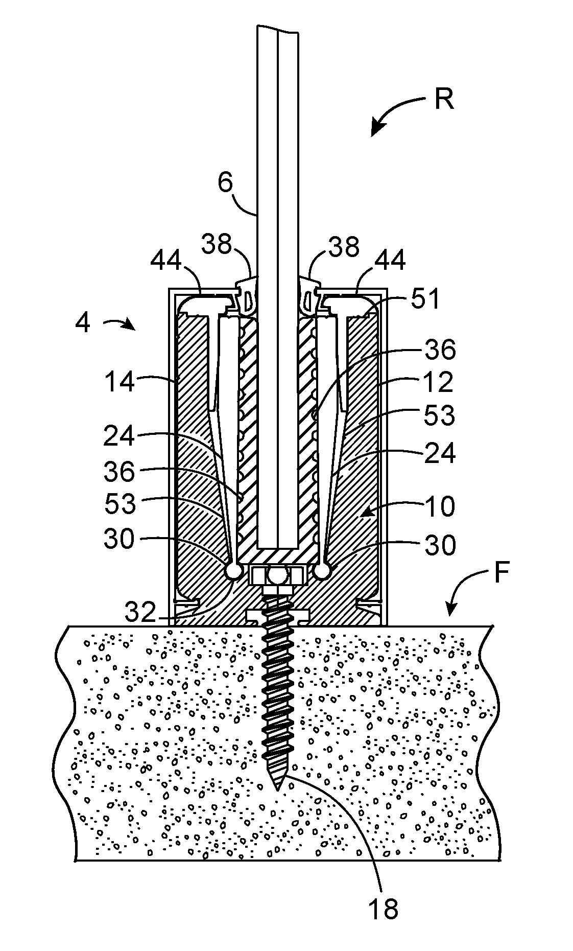
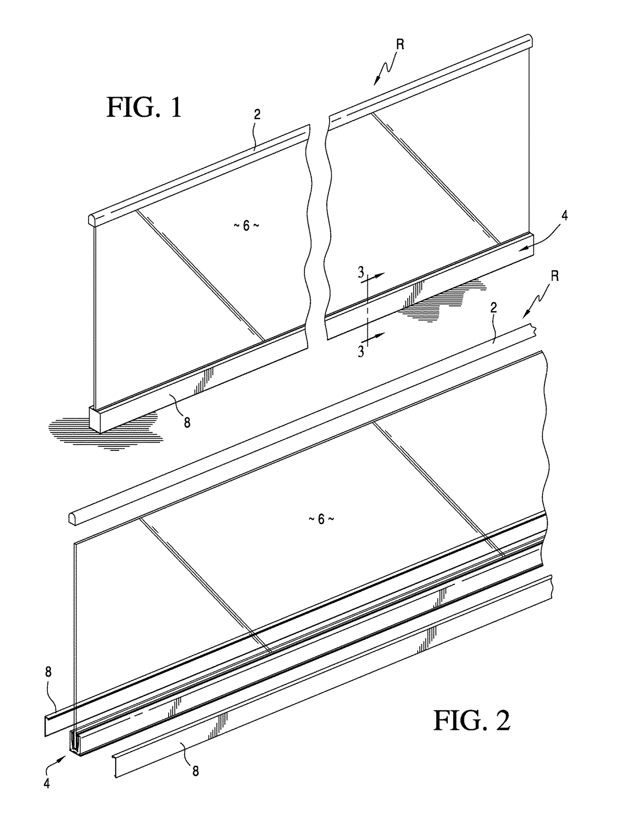
[0041]Turning to FIGS. 1 and 2, a glass panel railing R according to the present invention is shown. The railing has a top handrail 2 and a base member 4 at an opposite bottom end. A series of individual glass panels 6 are set into the base member 4, the structure of which will be further discussed below.

[0042]Glass panel 6 is of variable length as best shown in FIG. 1. It may comprise a single panel or multiple panels that are aligned in an end-to-end relation. The panels 6 are tempered glass having varying thickness, although they are typically ½ inch (0.0127 meters) to ¾ inch (0.01905 meters) in thickness. As is apparent, it is within the scope of the present invention to provide panels in handrail R that are constructed from materials other than tempered glass, such as plastic or various other materials.

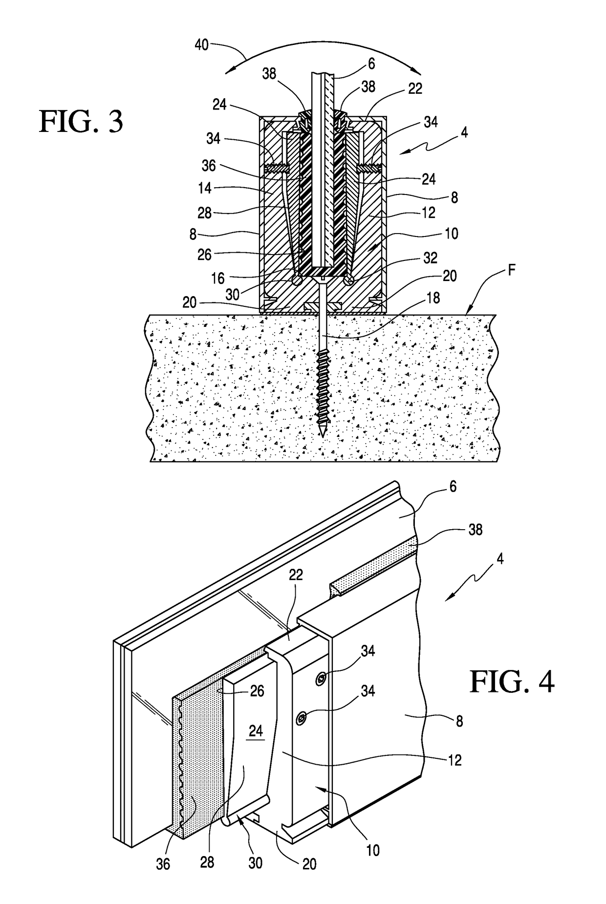
[0043]The present invention is shown in greater detail in FIGS. 3 and 4. An optional cover 8 may be provided on base member 4 and overlying sill member 10. The sill member 10 com...


PUM


Abstract

The invention is a double-hinged sill for adjustable securing the panels of a handrail system to a floor, the sill has U-shaped channel. A pair of hinged plates is pivotally mounted within the channel. A cylindrical hinge member is provided at the bottom end of each of the hinge plates and extends the length of the hinge plate. A groove for receiving the cylindrical hinge member is provided at the bottom of the sill. The pair of hinge plates is aligned within the sill as mirror images. A series of adjustment and locking screws are provided along the length of the sill and extend there through from either the top of the sill or the sides of the sill and a readapted to selectively impinge against the pair of hinge plates to movably adjust the plates inwardly against a glass panel or outwardly away from a glass panel to vertically align the same and lock it into place.

Description

CROSS-REFERENCE[0001]This application is a continuation-in-part of U.S. patent application Ser. No. 13 / 847,383 filed on Mar. 19, 2013. The entire contents of U.S. patent application Ser. No. 13 / 847,383 are hereby incorporated by reference.FIELD OF THE INVENTION[0002]This invention relates to handrails and more particularly, to a mounting system for securing a structural glass handrail to a floor.BACKGROUND OF INVENTION[0003]It is known to incorporate glass or other transparent panels within a guardrail or handrail to provide a functional and aesthetically pleasing railing. Generally speaking, such glass handrail systems comprise a series of vertically disposed glass panels that are aligned in an end-to-end relation. The bottom edges of the panels are fixed to the floor of the building while the top edges support a continuously extending top rail or handrail.[0004]The above noted glass handrail systems are difficult to install. In particular, a base member or sill for holding the ind...

Claims


Application Information

Patent Timeline
Patent Type & Authority Patents(United States)
IPC IPC(8): E04B1/00E04B5/00E04B7/00E04F11/18
CPCE04F11/1853E04F11/1812E04F2011/1823
Inventor HEADER, GREGORY A.
Owner SOLAR INNOVATIONS LLC
Why Eureka
Try Eureka