Substrate processing apparatus

a technology of substrate and processing apparatus, which is applied in the direction of vacuum evaporation coating, coating, electric discharge tube, etc., can solve the problems of difficult maintenance of the apparatus, and achieve the effect of suppressing the pressure change in the process space and high-quality thin film

Active Publication Date: 2017-10-03
CANON ANELVA CORP
View PDF20 Cites 2 Cited by
  • Summary
  • Abstract
  • Description
  • Claims
  • Application Information

AI Technical Summary

Benefits of technology

[0012]According to the present invention, it is possible to provide a technique capable of suppressing a pressure change in a process space when a substrate holder is moved and advantageous in depositing a high-quality thin film.

Problems solved by technology

In a sputtering apparatus, if a thin film is formed on the inner wall of the process chamber, maintenance of the apparatus becomes difficult.

Method used


Image

  • Substrate processing apparatus
  • Substrate processing apparatus
  • Substrate processing apparatus

Examples


example 1

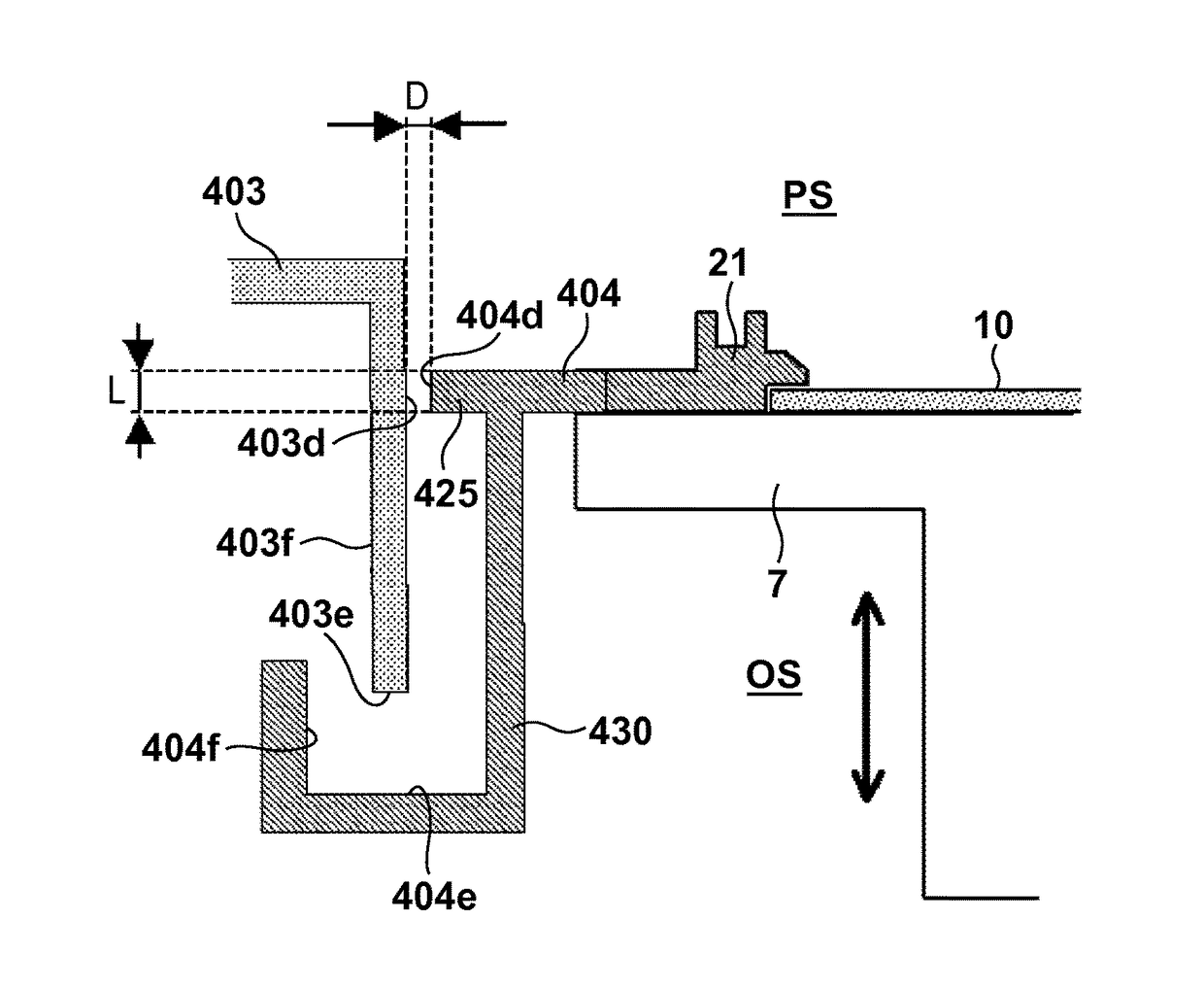
[0075]An example of the first embodiment of the present invention will be described with reference to FIG. 8. Referring to FIG. 8, the relationship to the TS distance was measured concerning the TS distance and the pressure in the shield when the minimum gap D was 6 mm, and the length L was 20 mm. As a comparative example, similar measurement was done for a sputtering apparatus described in PTL 1 in which the shield structure in the vicinity of the substrate holder changes along with a change in the TS distance. Graph 1 shows the result. In the experiments, Ar was introduced in the shield at 100 sccm, and the pressure in the shield was measured by a diaphragm type vacuum gauge at three positions corresponding to TS distances of 230 mm, 280 mm, and 330 mm. In the related art, the pressure changed from 1.103 Pa to 1.077 Pa. In the present invention, however, the change was suppressed within the range of 1.116 Pa to 1.104 Pa, as can be seen.

[0076]Note that in the embodiments, in additi...


PUM

PropertyMeasurementUnit
lengthaaaaaaaaaa
lengthaaaaaaaaaa
pressureaaaaaaaaaa

Abstract

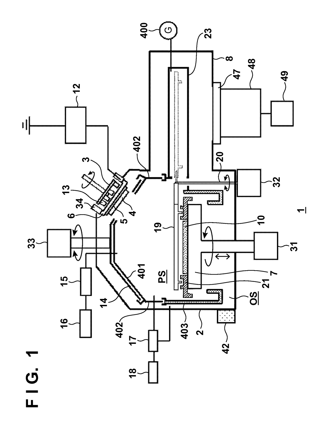
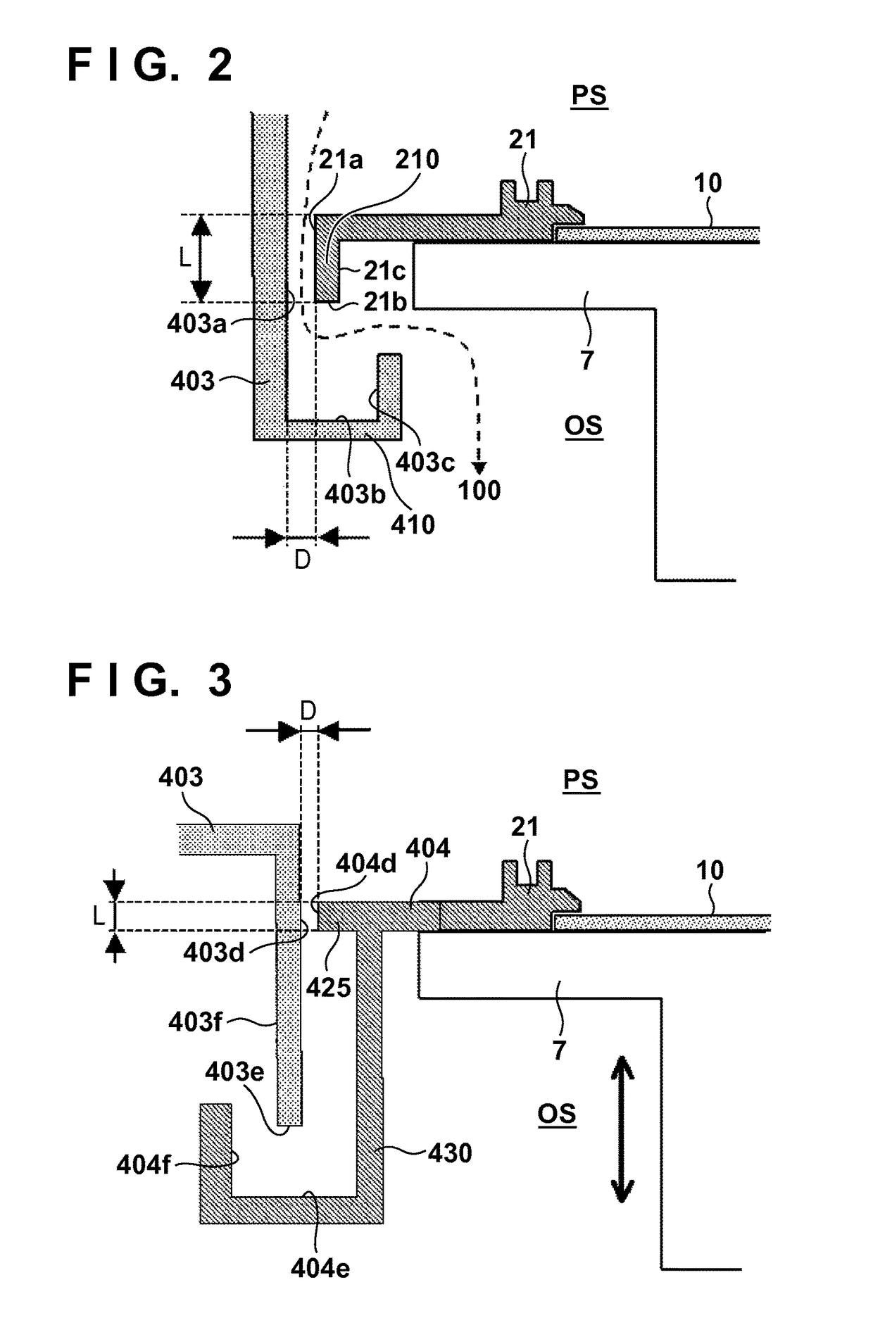
An apparatus includes a process chamber, a substrate holder arranged in the process chamber, a first shield provided on the peripheral portion of the substrate holder, and a second shield provided inside the process chamber. The internal space of the process chamber is partitioned into an outer space and a process space to process the substrate, by at least the first shield, the second shield, and the substrate holder. The substrate holder can be driven along a driving direction perpendicular to a substrate holding surface. The length, in a direction parallel to the driving direction, of a minimum gap portion having a minimum size in a direction perpendicular to the driving direction between the first and second shields does not change even if the substrate holder is driven in the driving direction.

Description

[0001]This application is a continuation of International Patent Application No. PCT / JP2013 / 006997 filed on Nov. 28, 2013, and claims priority to Japanese Patent Application No. 2012-282467 filed on Dec. 26, 2012, the entire content of both of which is incorporated herein by reference.TECHNICAL FIELD[0002]The present invention relates to a substrate processing apparatus.BACKGROUND ART[0003]In a sputtering apparatus, if a thin film is formed on the inner wall of the process chamber, maintenance of the apparatus becomes difficult. Hence, an interchangeable protection shield is placed in the process chamber to protect the inner wall. The distance between a target and a substrate (to be referred to as a TS distance hereinafter) is known to affect the evenness of the thickness or quality of a formed film. In addition, the film thickness or film thickness distribution tends to gradually degrade as the target is gradually sputtered, and erosion progresses, as is known. Concerning these phe...

Claims


Application Information

Patent Timeline
Patent Type & Authority Patents(United States)
IPC IPC(8): C23C14/34H01J37/34H01J37/32
CPCH01J37/3441C23C14/34H01J37/32477H01J37/32715H01J37/32733H01J37/3405H01J37/347C23C14/3492C23C14/50C23C14/54
Inventor SHIMANE, YOSHIMITSUUCHINO, SATOSHIAKIYAMA, SUSUMUMATSUO, KAZUAKIYAMAGUCHI, NOBUO
Owner CANON ANELVA CORP
Why Eureka
Try Eureka