
Anatomically guided instrumentation for trochlear groove replacement

a technology of trochlear groove and anatomic guide, which is applied in the field of positioning guide and bone preparation tools, can solve the problems of affecting the natural motion of the patella along the trochlear groove, affecting the precision of the operation, and difficulty in duplication by skilled surgeons

Active Publication Date: 2017-10-10
STRYKER CORP
View PDF18 Cites 18 Cited by
  • Summary
  • Abstract
  • Description
  • Claims
  • Application Information

AI Technical Summary

Benefits of technology

The present invention provides a prosthesis for replacing a trochlear groove region of a femur bone. The prosthesis has a bone contact surface with a plurality of protrusions for insertion into the femur bone. The protrusions have a spatial configuration with respect to one another. The prosthesis also includes a first template with a guide opening and a second template with at least one guide hole. The system also includes a bone punch instrument and a bone resection tool. The technical effects of the invention include improved stability, reduced bone damage, and improved outcomes for patients with femur bone injuries.

Problems solved by technology

Severe pain may result where the articular cartilage of the patella and / or the femoral trochlear groove is eroded or otherwise damaged and natural motion of the patella along the trochlear groove is impeded.
However, even a skilled surgeon may have trouble duplicating results where speed and precision are critical.
Therefore, one of the biggest drawbacks of current instrumentation is that each provides no true anatomically based means for guiding the surgeon to restore the trochlear groove or patellar track to ensure proper patellofemoral kinematics.
Further, certain existing patellofemoral implants have asymmetric designs and few sizing options, which frequently results in a poor anatomic fit.

Method used


Image

  • Anatomically guided instrumentation for trochlear groove replacement
  • Anatomically guided instrumentation for trochlear groove replacement
  • Anatomically guided instrumentation for trochlear groove replacement

Examples


Embodiment Construction

[0085]As used herein, the term “proximal” means closer to the heart, and the term “distal” means further from the heart. The term “anterior” means toward the front part of the body or the face, and the term “posterior” means toward the back of the body. The term “medial” means toward the midline of the body, and the term “lateral” means away from the midline of the body. F / E refers to flexion and extension rotation about the epicondylar axis of a femur bone. I / E refers to internal and external rotation about the longitudinal axis of the intramedullary canal of a femur bone.

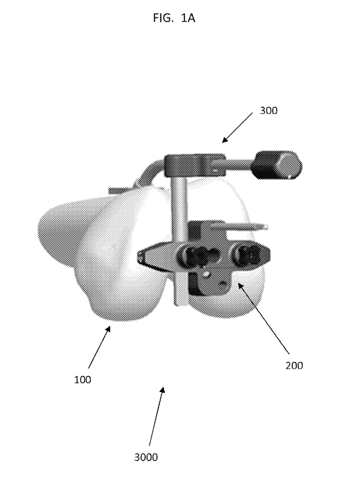
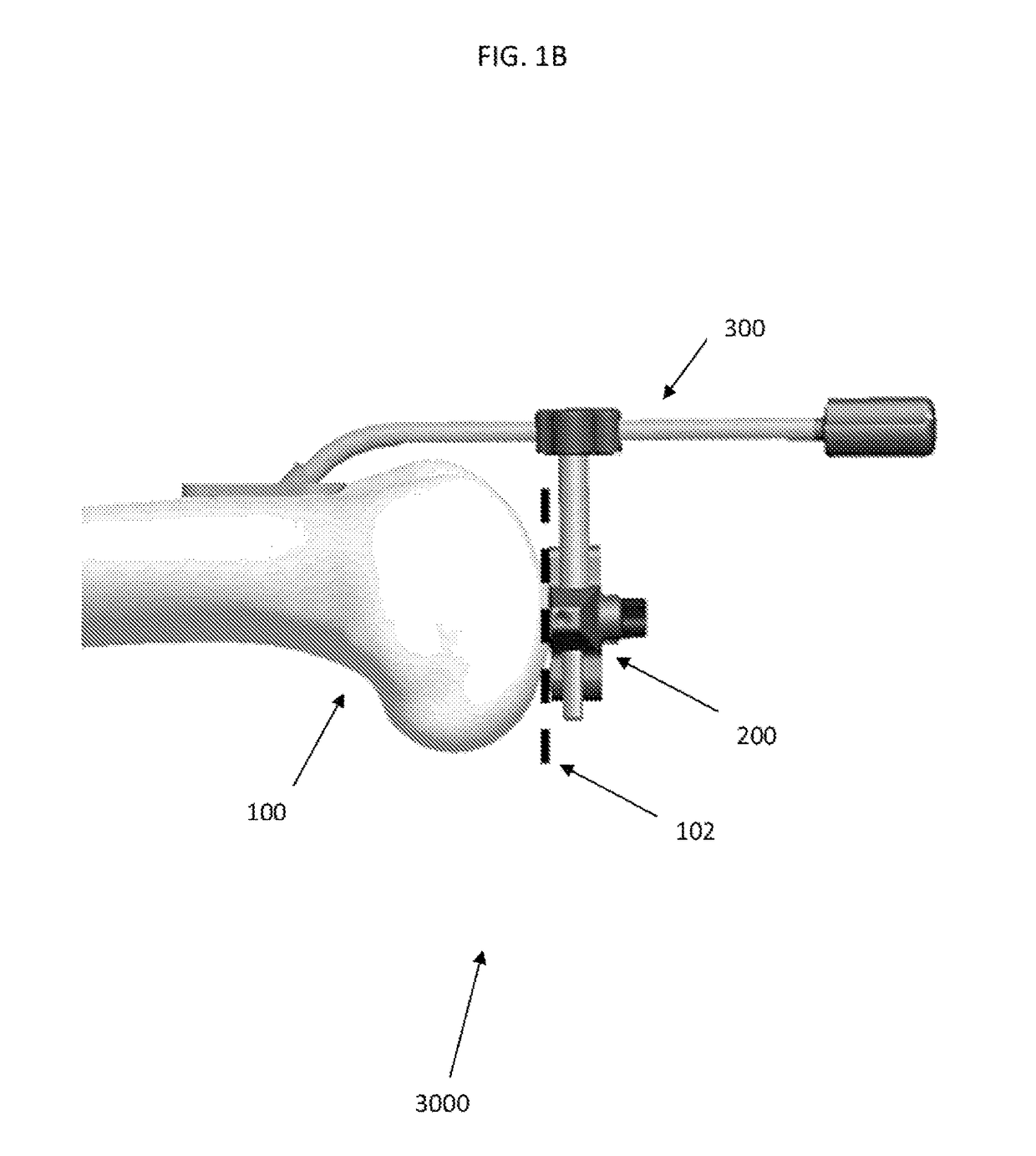
[0086]FIGS. 1A and 1B show an F / E alignment assembly 3000 in accordance with an embodiment of the present invention. The F / E alignment assembly 3000 includes an F / E stylus assembly 300 and an intercondylar block 200.

[0087]FIG. 2 shows the intercondylar block 200, which generally includes a lateral-medial (“L-M”) member 204, an anterior-posterior (“A-P”) member 214, and a plurality of holes. The plurality of holes ...


PUM


Abstract

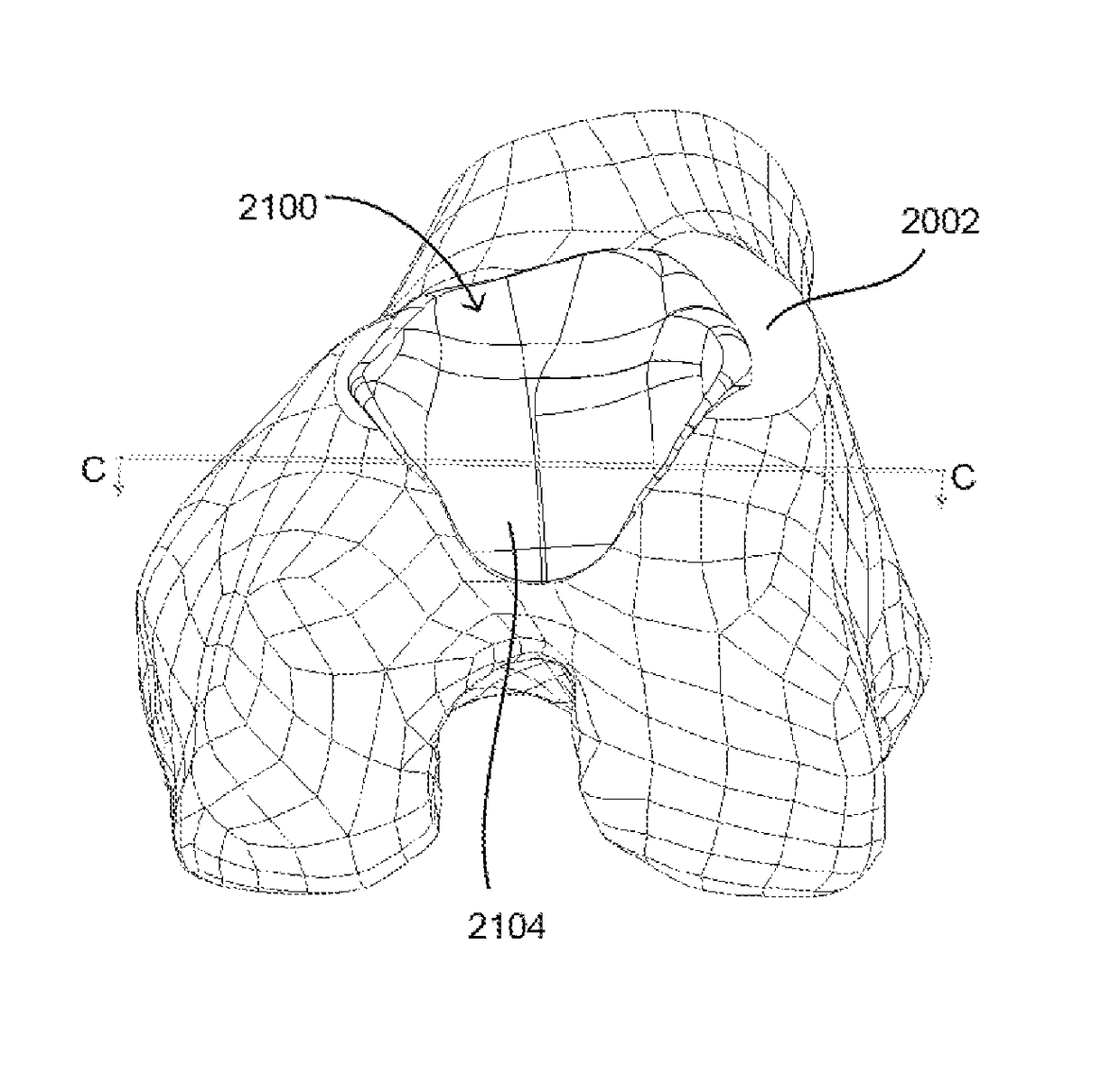
A method for replacing a joint surface, which includes resecting a first portion of the joint surface to create a wall surface and inner resected surface. The wall surface (2006) separates the inner resected surface and a non-resected portion of the joint surface. Further included in the method is cutting a concave groove having a first radius into the wall surface, and engaging the concave groove with a periphery of a joint prosthesis. The periphery includes a second radius that is substantially the same as the first radius of the concave groove.

Description

CROSS-REFERENCE TO RELATED APPLICATIONS[0001]The present application is a national phase entry under 35 U.S.C. §371 of International Application No. PCT / US2014 / 018300, filed Feb. 25, 2014, which claims priority from U.S. Provisional Application No. 61 / 893,548, filed Oct. 21, 2013 and from U.S. Provisional Application No. 61 / 768,765, filed Feb. 25, 2013, the disclosures of which are hereby incorporated herein by reference.FIELD OF THE INVENTION[0002]The present invention relates to systems and methods for use in patellofemoral knee replacement, and in particular, relates to positioning guides and bone preparation tools for preparation of the trochlear groove of a patient's femur and patellofemoral prostheses for implantation thereon.BACKGROUND OF THE INVENTION[0003]The knee joint is a tri-compartmental joint consisting of the medial and lateral compartments which make up the tibiofemoral joint (“TFJ”) and the patellofemoral compartment which makes up the patellofemoral joint (“PFJ”)....

Claims


Application Information

Patent Timeline
Patent Type & Authority Patents(United States)
IPC IPC(8): A61F2/38A61B17/16A61B17/17A61B34/30A61B17/15A61F2/30
CPCA61F2/3859A61B17/1604A61B17/1675A61F2/3877A61B17/1764A61F2002/30878A61B17/155A61B34/30
Inventor COLLAZO, CARLOS E.AXELSON, JR., STUART L.FERKO, MICHAEL C.HAMPP, EMILY
Owner STRYKER CORP
Learn More