Motor vehicle door lock

a technology for motor vehicles and door locks, applied in the direction of electrical locking circuits, mechanical devices, lock applications, etc., can solve the problems of adverse effects on the perceived comfort, and reducing the power requirements of the door locking mechanism, so as to improve the comfort and quality of the locking mechanism and its functionality, reduce the effect of power requirements and reduced overall construction cos

Active Publication Date: 2017-10-10
HUF HULSBECK & FURST GMBH & CO KG
View PDF6 Cites 2 Cited by
  • Summary
  • Abstract
  • Description
  • Claims
  • Application Information

AI Technical Summary

Benefits of technology

[0010]This invention provides a vehicle door locking mechanism, which serves to contribute to an increase in comfort and quality of locking mechanisms and their functionality. The vehicle door locking mechanism in accordance with this invention is characterized by a functional design and features a simple, cost-effective and compact overall construction.
[0011]With the trigger mechanism in accordance with the invention, the drive element moves the locking pawl in the direction of the release position during the movement to the opening position in such a way that the rotary pawl, which is still engaged with the rotary latch as before, moves in the direction of the opening position. Given the trigger mechanism of the motor vehicle door lock in accordance with the concerned invention, the locking pawl and the rotary latch are still engaged with one another during the movement of the locking pawl in the direction of the release position. This movement of the locking pawl does, however, not allow for the opening of the tailgate. But this motion (the first or initial one) does, on the other hand, cause the pre-stress of the tailgate to be relieved during the opening process, due to the fact that the defined motion of the locking pawl causes a relative motion between the motor vehicle door lock and the locking element and therefore results in a pressure relief for the tailgate, causing the rotary latch to be rotated to the opening position by a predetermined rotary movement. This ultimately allows the tailgate to be moved by a predefined stroke relative to the locking element, which results in the pre-stress and the pressure to be relieved that had been responsible for the audible and annoying opening noise experienced with door locking mechanisms of the past. The invention therefore allows the pre-stress between the tailgate or the vehicle door locking mechanism and the locking element to be reduced before the locking pawl and the rotary latch are moved out of engagement.
[0012]Regarding annoying rattling noises of the locking element held within the rotary latch, the invention provides an immobilization element to alleviate these issues often encountered with previous door locking mechanisms. This immobilization element causes the locking element to be clamped between the rotary latch and the immobilization element in the locking position of the rotary latch so that a relative motion of the locking element, which is responsible for the annoying rattling noise, is prevented. In order to ensure that the clamping force does not oppose the opening of the vehicle door locking mechanism, the immobilization element is coupled to the rotary latch, which ensures that a movement of the rotary latch out of the locking position into the opening position also causes the immobilization element to be moved accordingly an...

Problems solved by technology

The motor of the drive element therefore has to be dimensioned accordingly, though the smallest possible and therefore less powerful ones are preferred, which then reduces the power requirements of the door locking mechanism again.
If the locking pawl is no longer engaged with the rotary latch, the pressure that has built up due to the sealing in the form of a so-called “discharge blow” and the tailgate suddenly and abruptly moves towards the openi...

Method used


Image

  • Motor vehicle door lock
  • Motor vehicle door lock
  • Motor vehicle door lock

Examples


Embodiment Construction

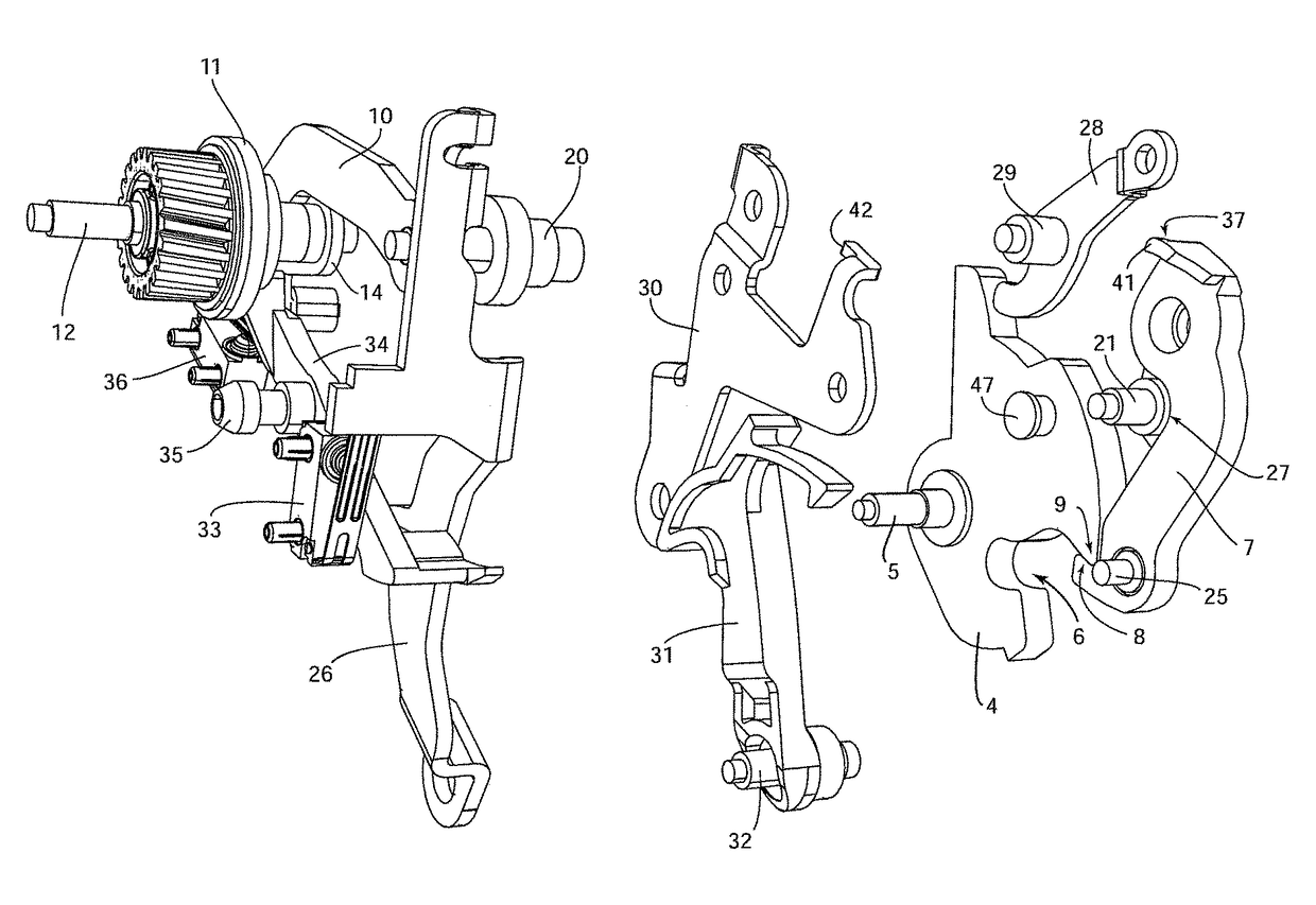
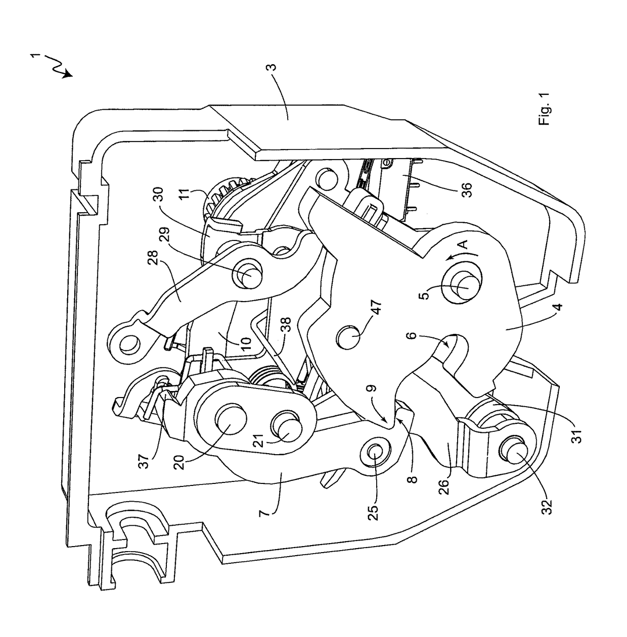
[0047]FIG. 1 contains a perspective view of the motor vehicle door locking mechanism “1”, in particular a tailgate lock assembly, in accordance with the invention. The motor vehicle door lock “1” that can be mounted on the tailgate of a motor vehicle, engages with a locking element “2”, which is only schematically portrayed in FIGS. 4 and 13, for the purpose of closing and locking the tailgate. The locking element “2” could be designed as a locking bolt or locking clip and be mounted on the vehicle frame. The vehicle door locking mechanism “1” comprises a housing element “3”, which is used to mount and house additional components of the vehicle door locking mechanism “1”. In order to prevent visual obstructions, the housing element “3” is merely portrayed in FIG. 1. As can be seen in FIGS. 1 to 5, the motor vehicle door locking mechanism “1” also comprises a rotary latch “4”, which is rotationally mounted on the housing element “3” around a locationally fixed rotary axis “5” and is ...


PUM


Abstract

A motor vehicle door lock includes a rotary latch which in a locking position encompasses a locking element that is pre-tensioned in a direction of an open position releasing the locking element. A pawl is in engagement with the rotary latch such that the latch is inhibited from moving towards the open position. A coupling section of the pawl is coupled to a drive element which moves the pawl between an engagement position and a release position, the release position allowing the rotary latch to move toward the open position. A force is applied to the pawl only in the engagement position thereof and the force application holds the pawl in engagement with the rotary latch.

Description

BACKGROUND[0001]This invention concerns a motor vehicle door lock mechanism with a rotary latch that surrounds a locking element in the device's locking position and that is preloaded in the direction of the locking element when the device is in the open position, a locking pawl that is positioned in relation to the rotary latch when in the engagement position in such a way that the rotary latch is prevented from moving in the direction of the open position, and a drive element, which is used to couple a coupling section of the locking pawl and that moves the locking pawl between the engagement position and a release position, at which the locking pawl is not engaged with the rotary latch so that the rotary latch can move in the direction of the open position.[0002]A motor vehicle door locking mechanism of the aforementioned kind is, for example, recognized in DE 10 2007 024 672 Al and is, among other fields, used for tailgates of motor vehicles. Such a motor vehicle door lock compr...

Claims


Application Information

Patent Timeline
IPC IPC(8): E05C3/06E05B77/36E05B85/20E05B81/14E05B81/68E05B15/04E05B77/06E05B85/26E05B81/20E05B47/00
CPCE05B85/20E05B15/04E05B77/36E05B81/14E05B81/68Y10T292/1043E05B77/06E05B81/20E05B85/26E05B2047/0065E05B81/06E05B83/18
Inventor TORKA, ARTURORZECH, UDOWIETKAMP, STEPHAN
Owner HUF HULSBECK & FURST GMBH & CO KG
Why Eureka
Try Eureka