Electric stove

a stove and electric technology, applied in the field of electric stoves, can solve the problems of thermal efficiency loss and far from satisfactory reflection efficiency of heat rays on the mirror surface portion, and achieve the effect of increasing the reflection efficiency of heat rays and reducing thermal efficiency loss

Inactive Publication Date: 2017-10-10
TAKITA RES & DEV
View PDF8 Cites 0 Cited by
  • Summary
  • Abstract
  • Description
  • Claims
  • Application Information

AI Technical Summary

Benefits of technology

[0031]According to the present invention, an electric stove is obtained which is further improved to be able to further reduce a loss in terms of thermal efficiency by further increasing the reflection efficiency of heat rays on a mirror surface portion.

Problems solved by technology

However, in this electric stove, not all the heat rays radiated from the electric heating element and reflected by the partial elliptical mirror surface portion, the first and second reflecting mirror surface portions are efficiently radiated to a laying member such as a baking rack on which the target to be heated is placed, but there are heat rays accumulated in the electric stove.
Since there is a loss in terms of thermal efficiency, the reflection efficiency of the heat rays on the mirror surface portion is far from satisfactory.

Method used


Image

  • Electric stove
  • Electric stove
  • Electric stove

Examples


first embodiment

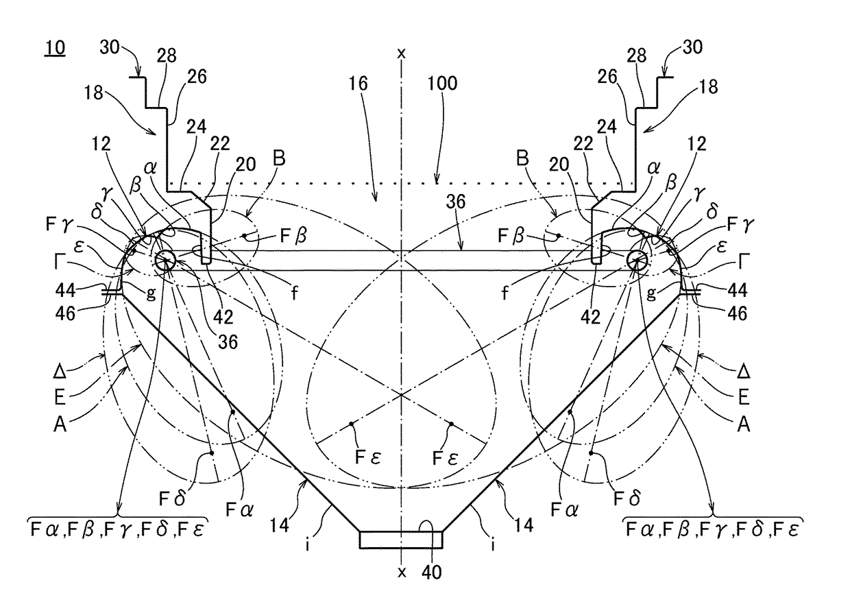
[0097]In an electric stove according to this embodiment, the object to further reduce a loss in terms of thermal efficiency by further increasing the reflection efficiency of heat rays radiated from an electric heating element on a first mirror surface portion and a second mirror surface portion is achieved by reflecting heat rays on a first mirror surface portion including a plurality of partial elliptical mirror surface portions having one focus near an arrangement position of the electric heating element and a second mirror surface portion including a single partial elliptical mirror surface portion having one focus at the same position as the former focus to collect the heat rays to a side below a target to be heated by reflecting the heat rays substantially immediately upwardly.

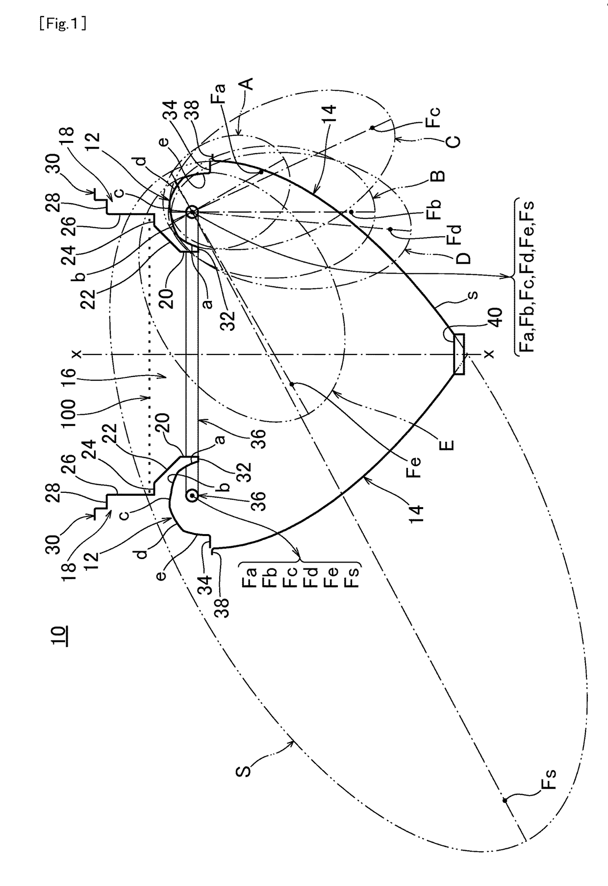
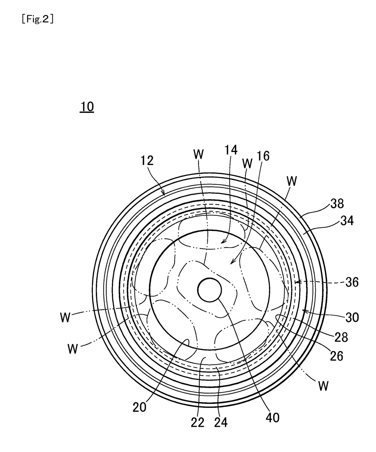
[0098]FIG. 1 is a schematic front view in section showing an example of the embodiment of the present invention, and FIG. 2 is a schematic plan view of the embodiment shown in FIG. 1. Further, FIGS. 3 to...

second embodiment

[0125]FIG. 10 is a schematic front view in section showing another example of the embodiment of the present invention, and FIG. 11 is a schematic plan view of the embodiment shown in FIG. 10. Further, FIGS. 12 to 20 are explanatory diagrams showing reflection paths of heat rays radiated from electric heating elements when targets to be heated were heated using an electric stove according to the embodiment shown in FIGS. 10 and 11.

[0126]An electric stove 10 according to this embodiment (second embodiment) differs from the embodiment (first embodiment) described above with reference to FIGS. 1 to 9 particularly in the configuration of the first mirror surface portion 12. In this case, in the embodiment (first embodiment) shown in FIGS. 1 to 9, the first mirror surface portion 12 is formed, for example, by the five partial elliptical mirror surface portions (first to fifth partial elliptical mirror surface portions a to e) and the other focuses Fa to Fe of these first to fifth partial ...


PUM


Abstract

An electric stove includes an electric heating element arranged at a distance from a position right below a target to be heated. A first mirror surface portion is arranged to surround the electric heating element and configured to reflect heat rays radiated from the electric heating elements. A second mirror surface portion is arranged below the electric heating elements and configured to collect the heat rays reflected by the first mirror surface portion to a side below the target by reflecting the heat rays substantially immediately upwardly. The first mirror surface portion includes a plurality of partial elliptical mirror surface portions having one focus near the electric heating elements and the other focus below the electric heating elements, and the second mirror surface portion includes a partial elliptical mirror surface portion a having one focus near the electric heating elements and the other focus below the electric heating elements.

Description

TECHNICAL FIELD[0001]The present invention relates to an electric stove, particularly to an electric stove for heating a target to be heated by radiation heat, for example, used to cook fish, meat, vegetable, bread and other foods.BACKGROUND ART[0002]Various electric stoves capable of suppressing the production of smoke have been proposed by the present inventor as background conventional technology of the present invention (see, for example, patent literature 1).[0003]This electric stove includes an electric heating element such as a sheathed heater provided at a distance from a position right below a target to be cooked (hereinafter, referred to as a “target to be heated”) and a mirror surface portion for collecting heat rays radiated from the electric heating element to a side below the target to be heated. This mirror surface portion is configured to include a partial elliptical mirror surface portion which has one focus near the electric heating element and reflects the heat ra...

Claims


Application Information

Patent Timeline
Patent Type & Authority Patents(United States)
IPC IPC(8): A21B1/00F24C15/22F24C7/06A47J37/07
CPCF24C7/065F24C15/22A47J37/0709F24C7/046A47J37/06
Inventor TAKITA, MASAAKI
Owner TAKITA RES & DEV
Why Eureka
Try Eureka