Air supply damper for separately supplying leakage air flow and supplementary air flow, method for controlling the same, and smoke control system utilizing the same

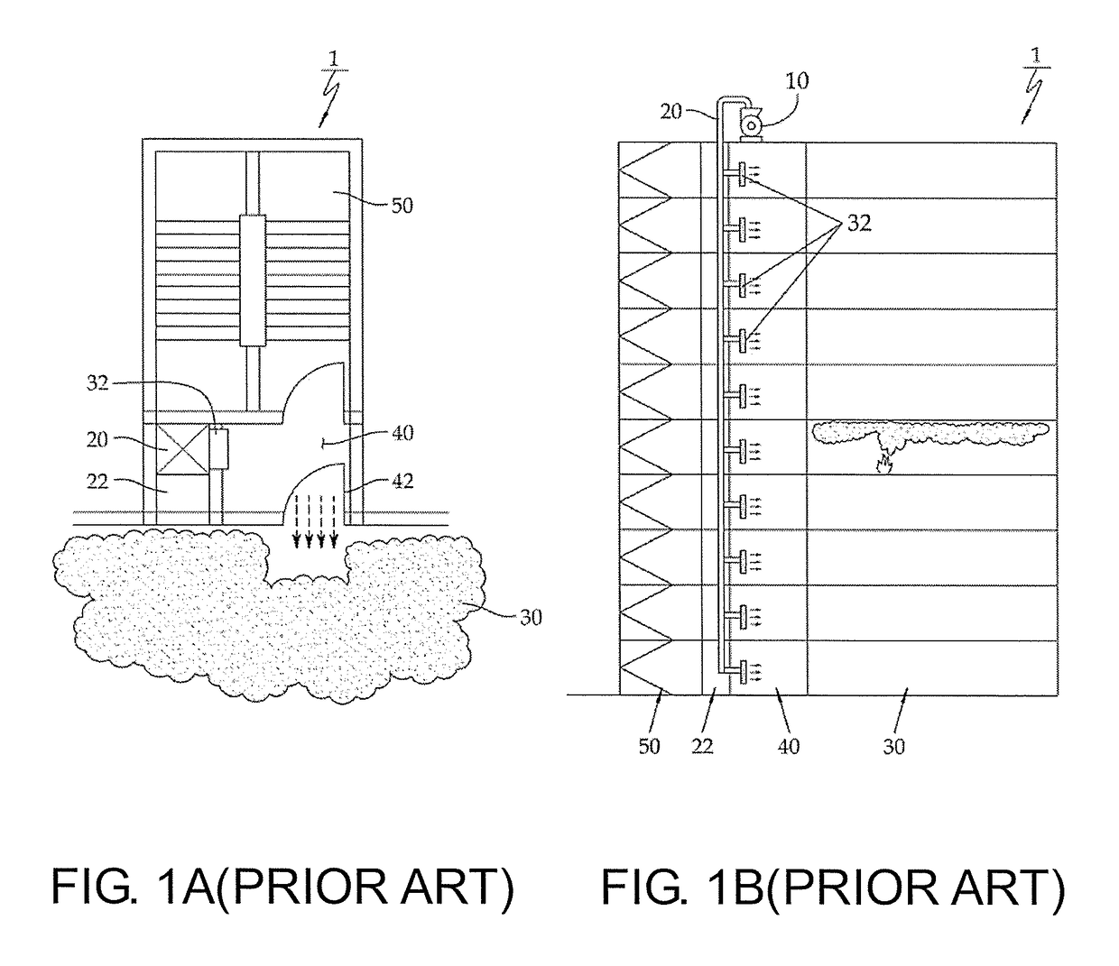
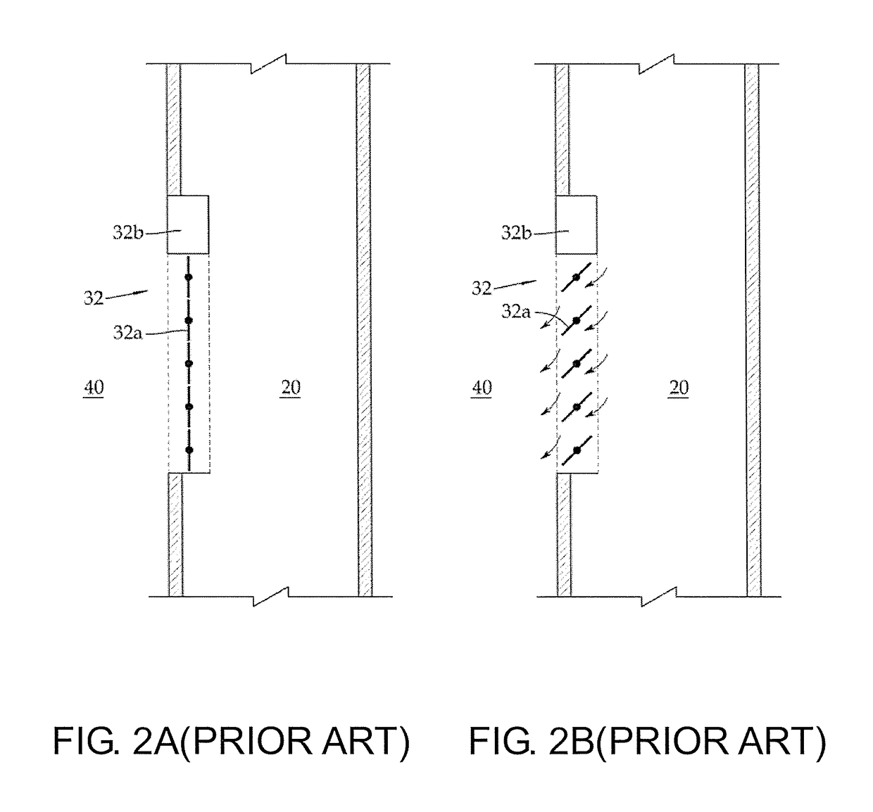
a technology of leakage air and damper, which is applied in the direction of ventilation systems, lighting and heating apparatuses, heating types, etc., can solve the problems of significant threat to life, and the performance of pressurized smoke control systems b>1/b> in a considerable number of buildings, and achieve the effect of effectively preventing differential pressure generation and properly maintaining differential pressur

Active Publication Date: 2017-10-10
KOREA INST OF CIVIL ENG & BUILDING TECH
View PDF9 Cites 4 Cited by
  • Summary
  • Abstract
  • Description
  • Claims
  • Application Information

AI Technical Summary

Benefits of technology

[0053]According to the present invention, leakage air flow and supplementary air flow are supplied into a lobby provided on each floor of a high-rise building through separate flow passages, respectively, and so when a fire occurs in the building, it is possible to effectively prevent differential pressure generated between the lobby and the accommodation from becoming lower or higher than the design standard, and to provide safety evacuation conditions.
[0054]In addition, according to the present invention, since the pressure-sensing sensor is mounted in the lobby and the accommodation of the building for sensing pressure, and the automatic opening / shutting device is mounted in the air supply damper (the leakage air flow supplying damper and the supplementary air flow damper having the function of supplying separately leakage air flow and supplementary air flow), it is possible to more properly maintain the differential pressure formed between the lobby and the accommodation, and to provide safety evacuation conditions when a fire occurs.

Problems solved by technology

In particular, the importance of a smoke control system for controlling smoke, which causes inconvenience during evacuation and fire extinguishing activities and poses a significant threat to the safety of life when a fire occurs in a building, has been emphasized.
However, after reviewing a result of the in-site performance evaluation of the pressurized smoke control system 1 installed and operated in the real building, it is found that the pressurized smoke control systems 1 in the considerable number of buildings do not show the designed performances.

Method used


Image

  • Air supply damper for separately supplying leakage air flow and supplementary air flow, method for controlling the same, and smoke control system utilizing the same
  • Air supply damper for separately supplying leakage air flow and supplementary air flow, method for controlling the same, and smoke control system utilizing the same
  • Air supply damper for separately supplying leakage air flow and supplementary air flow, method for controlling the same, and smoke control system utilizing the same

Examples


Embodiment Construction

[0062][Mode for Invention]

[0063]Hereinafter, the preferred embodiment of the present invention will be described in more detail with reference to the accompanying drawings.

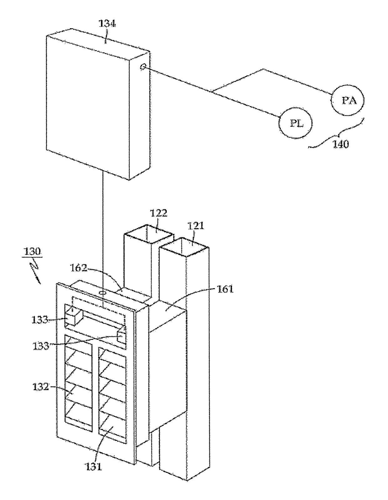
[0064]A smoke control system 100 for a high-rise building according to the present invention is the smoke control system 100 for separately supplying leakage air flow and supplementary air flow into a lobby 40 of a building 101.

[0065]As shown in FIG. 3, the smoke control system 100 for a high-rise building according to the present invention is provided with a blowing means 110 for supplying air into the building 101, and such blowing means 110 includes a leakage air flow supplying blower 111 and a supplementary air flow supplying blower 112.

[0066]The smoke control system is also provided with a ventilating means 120 having a leakage air flow supplying passage and a supplementary air flow supplying passage, each of which being connected to the blowing means 110 to allow air to be entered.

[0067]The above ventilating...


PUM


Abstract

Disclosed is a smoke control system provided in a high-rise building for separately supplying leakage air flow and supplementary air flow, including: a blowing means for supplying air into a building; a ventilating means having a leakage air flow supplying passage and a supplementary air flow supplying passage connected to the blowing means for introducing air; and an air supply damper connected to the leakage air flow supplying passage and the supplementary air flow supplying passage to supply air into each lobby of a building according to the leakage air flow and supplementary air flow.

Description

CROSS-REFERENCE TO RELATED APPLICATION[0001]This application is a 371 of international application of PCT application serial no. PCT / KR2011 / 007889, filed on Oct. 21, 2011, which claims the priority benefit of Korean application no. 10-2010-0106294, filed on Oct. 28, 2010. The entirety of each of the above-mentioned patent applications is hereby incorporated by reference herein and made a part of this specification.BACKGROUND OF THE DISCLOSURE[0002]Technical Field[0003]The present invention relates to an air supply damper employed in a smoke control system provided in a high-rise building, and more particular, to an air supply damper having a function for separately supplying leakage air flow and supplementary air flow, which is connected to a utility-pipe conduit which separately supplies leakage air flow and supplementary air flow, to separately adjust the supply of leakage air flow and supplementary air flow for preventing in advance, differential pressure between an accommodation...

Claims


Application Information

Patent Timeline
Patent Type & Authority Patents(United States)
IPC IPC(8): F24F13/14F24F11/00F24F11/04
CPCF24F11/0086F24F2011/0095F24F2011/0042F24F11/04F24F11/30F24F2110/40F24F11/33F24F11/74F24F11/62
Inventor KIM, JUNG-YUPSHIN, HYUN-JOON
Owner KOREA INST OF CIVIL ENG & BUILDING TECH
Why Eureka
Try Eureka