Method for detecting light sources operated in pulsed mode

a technology of pulsed mode and light source, which is applied in the field of pulsed mode light source detection, can solve the problems the problem of affecting the detection accuracy of pulsed light source, so as to prevent the dazzling of other drivers, detect and recognize faster or more reliably

Active Publication Date: 2017-10-10
CONTI TEMIC MICROELECTRONIC GMBH
View PDF16 Cites 1 Cited by
  • Summary
  • Abstract
  • Description
  • Claims
  • Application Information

AI Technical Summary

Benefits of technology

[0030]Relevant light sources operated in pulsed mode may in particular be variable message signs, traffic lights, or road traffic signal systems, the information content of which can be detected and recognized faster or more reliably using the method according to the inv

Problems solved by technology

Use of LEDs (light-emitting diodes) instead of light bulbs as lamps presents a greater challenge to camera-based driver assistance systems.
Such pulsed light sources or light sources operated in pulsed mode can be problematic for camera-base

Method used


Image

  • Method for detecting light sources operated in pulsed mode
  • Method for detecting light sources operated in pulsed mode

Examples


Embodiment Construction

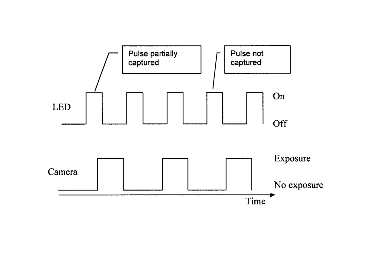
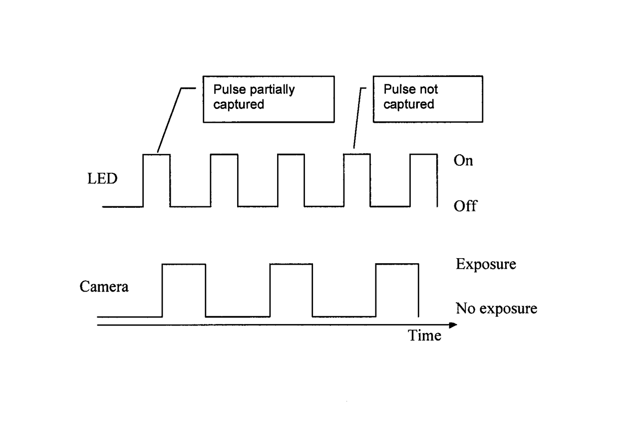
[0034]An LED that is switched on and off at regular intervals is shown as an example of a light source (upper curve). This pulsed operation is designed as pulse width modulation and has two parameters, the pulse rate and the duty cycle. The duty cycle indicates the percentage of a cycle in which the LED is on. In the example shown, the LED is on less than 50% of the time. The pulse rate is typically fixed in a given system. The duty cycle is used to control the lamp output in such lighting systems, which sets the brightness of the light.

[0035]The lower curve shows the development of the exposure phases of a camera over time. In prior art cameras, this development is also based on a fixed time pattern, e.g. a new exposure phase starts every 40 ms at an image-taking rate of 25 Hz. The exposure operation of the camera can therefore also be considered a pulsed operation.

[0036]As such systems typically use an optical system with a fixed focal length and aperture, the exposure time is ava...


PUM


Abstract

In a method for detecting light sources operated in pulsed mode using a camera, the camera records a series of images, and the time interval between two successive recordings of individual images is varied while the series of images is recorded.

Description

FIELD OF THE INVENTION[0001]This invention relates to a method for detecting light sources operated in pulsed mode using a camera, which can in particular be used in camera-based driver assistance systems.BACKGROUND INFORMATION[0002]Automatic camera-based driver assistance systems capture the vehicle surroundings using at least one camera, interpret the image data obtained, and use it to determine a system-specific response from it. Interpretation of the vehicle surroundings includes the detection of luminescent or illuminated elements of the infrastructure or of road traffic. Examples are traffic lights, traffic signs, headlights, and tail lights.[0003]Use of LEDs (light-emitting diodes) instead of light bulbs as lamps presents a greater challenge to camera-based driver assistance systems. Such LEDs are typically not operated continuously but switched on and off in pulsed mode. This means that they are not constantly lit but emit a rapid sequence of light flashes which, due to the ...

Claims


Application Information

Patent Timeline
IPC IPC(8): H04N7/18G06T7/00H04N5/235B60W30/00
CPCH04N5/2357B60W30/00G06T7/97H04N5/2353G06T2207/30252B60W2550/00G06T2207/10004G06T2207/10144G06T2207/30232B60W2420/42H04N23/745H04N23/73B60W2555/00
Inventor KRISTENSEN, STEENZOBEL, MATTHIASWINTERMANTEL, MARKUS
Owner CONTI TEMIC MICROELECTRONIC GMBH
Why Eureka
Try Eureka