Charging device for a vehicle mounted electrical storage device

a charging device and electrical storage technology, applied in the direction of electric devices, driver interactions, propulsion using engine-driven generators, etc., can solve the problems of user difficulty in realizing abnormalities, timer setting cannot be cancelled, instant charging cannot be carried out, etc., to achieve any troublesome burden on the user

Active Publication Date: 2017-10-17
TOYOTA JIDOSHA KK
View PDF11 Cites 0 Cited by
  • Summary
  • Abstract
  • Description
  • Claims
  • Application Information

AI Technical Summary

Benefits of technology

[0010]The invention provides a charging device for a vehicle, which increases the possibility that a failure on timer setting for charging is realized.
[0021]According to the invention, it is possible to increase the possibility that a failure on timer setting for charging is realized and to switch between enabled and disabled states of a timer in the flow of charging operation without any troublesome burden on a user.

Problems solved by technology

Thus, the frequency at which an input switch for issuing a command is operated is also low, and the user is hard to realize an abnormality even when the switch has a failure.
Therefore, in the case where the timer is set, when instant charging is intended by cancelling the timer setting; there is a concern that the timer setting cannot be cancelled and the instant charging cannot be carried out.

Method used


Image

  • Charging device for a vehicle mounted electrical storage device
  • Charging device for a vehicle mounted electrical storage device
  • Charging device for a vehicle mounted electrical storage device

Examples


first embodiment

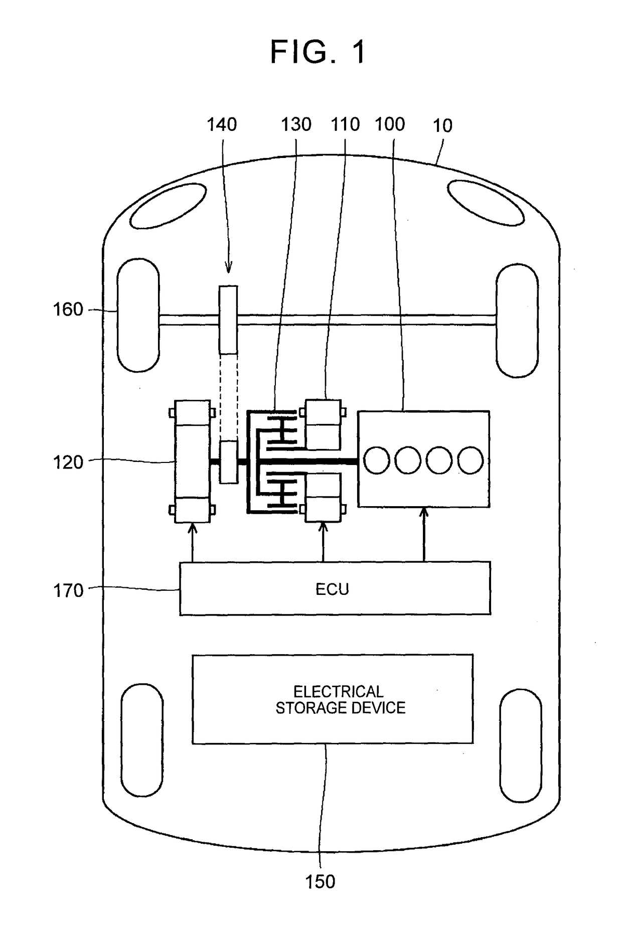
[0045]First, the configuration of an externally chargeable vehicle will be described. FIG. 1 is an overall block diagram of a hybrid vehicle that is shown as an example of the vehicle according to the embodiment of the invention. In the following description, the hybrid vehicle may be simply referred to as “vehicle”. In addition, the hybrid vehicle is illustrative. The invention is also applicable to an electric vehicle, a fuel-cell vehicle, and the like, as long as an electrical storage device is mounted on the vehicle and the vehicle is configured to be chargeable from a device outside the vehicle.

[0046]As shown in FIG. 1, the hybrid vehicle 10 includes an engine 100, a motor generator (MG) 110, an MG 120, a power split mechanism 130, a speed reduction gear 140, an electrical storage device 150, drive wheels 160 and an electronic control unit (ECU) 170.

[0047]The engine 100, the MG 110 and the MG 120 are coupled to the power split mechanism 130. The hybrid vehicle 10 travels on dr...

second embodiment

[0123]However, it is presumable that, depending on the user, a frequency at which timer charging is carried out is low. In the second embodiment, the case where the charging system is designed or set so as not to carry out timer charging even when the time of the timer is set unless otherwise specified and so as to carry out timer charging only when operation to enable the timer is performed will be described. In such a case, a switch for enabling the timer (hereinafter, referred to as timer determination switch) is required instead of the timer cancellation switch.

[0124]The configurations shown in FIG. 4 and FIG. 5 are also the same in the second embodiment. However, the way of usage of the switch 177 regarding timer setting is different.

[0125]FIG. 12 is a flowchart for illustrating how the ECU uses the switch in different ways according to the second embodiment. As shown in FIG. 4 and FIG. 12, initially, when the process is started, the ECU 170 determines in step S21 whether the c...

third embodiment

[0145]FIG. 18 is a flowchart for illustrating how the ECU uses the switch in different ways according to the As shown in FIG. 16 and FIG. 18, initially, when the process is started, the ECU 170 determines in step S21 whether the charging cable is connected to the inlet 250. The ECU 170 is able to determine whether the charging cable unit 300 is connected on the basis of the state of the signal PISW or the signal CPLT shown in FIG. 3.

[0146]In step S51, when it is determined that the charging cable unit 300 is not connected to the inlet 250, the process proceeds to step S52; whereas, when it is determined that the charging cable unit 300 is connected, the process proceeds to step S53.

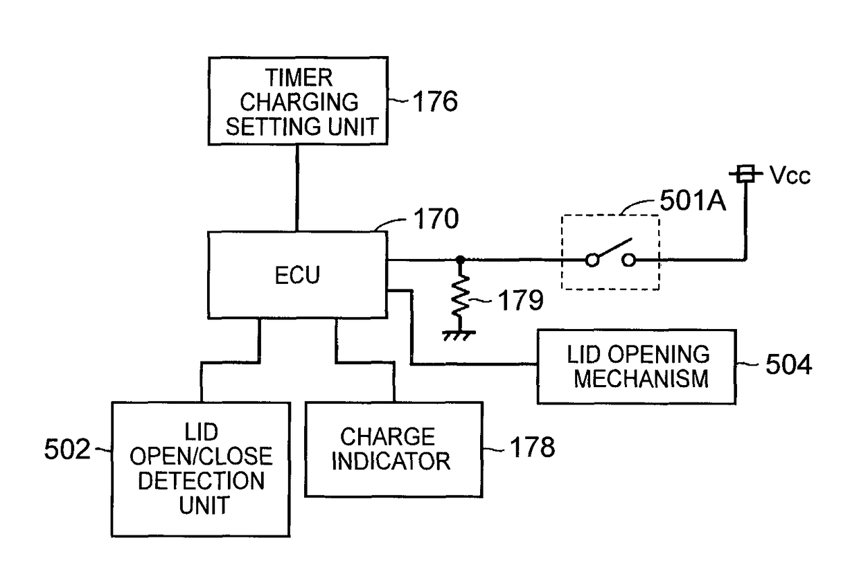
[0147]In step S52, the ECU 170 determines whether a lid open / close detection unit 502 has detected that the lid is open. In step S52, when it has been detected that the lid is open, the process proceeds to step S53; whereas, when it has been detected that the lid is closed, the process proceeds to step S...


PUM


Abstract

A charging device for a vehicle carries out timer charging in which the charging device is set in a standby state without charging until charging start time comes when the charging start time is set for a vehicle-mounted electrical storage device. The charging device for the vehicle includes a charger that charges the electrical storage device with electric power supplied from a device outside the vehicle, and an ECU that determines whether to carry out timer charging or carry out instant charging without carrying out the timer charging on the basis of a state of a switch associated with an open / close state of a charging lid, and that controls the charger. Desirably, a timer cancellation or determination switch is also used as a switch for detecting the open / close state of the lid or a switch for opening the lid.

Description

BACKGROUND OF THE INVENTION[0001]1. Field of the Invention[0002]The invention relates to a charging device for a vehicle on which an electrical storage device is mounted and, more particularly, to a charging device for a vehicle, which carries out timer charging.[0003]2. Description of Related Art[0004]In recent years, vehicles, such as electric vehicles and plug-in hybrid vehicles, configured to be able to charge a vehicle-mounted electrical storage device from an external device have started being widely used.[0005]Japanese Patent Application Publication No. 2012-70623 (JP 2012-70623 A) describes a control device for a vehicle, which is able to adjust a charging schedule for charging an electrical storage device from an external power supply.[0006]An ECU mounted on the vehicle described in this publication includes a charge control unit that causes a battery to be charged by controlling a charger and a start-up command unit that, when charging start time is set, issues a start-up ...

Claims


Application Information

Patent Timeline
Patent Type & Authority Patents(United States)
IPC IPC(8): H02J7/00B60L7/14B60L15/00B60L15/20B60L3/04B60L3/00B60L11/14B60L11/18H01H13/14B60L11/12B60L50/15B60L50/16
CPCB60L11/1851B60L3/003B60L3/0069B60L3/04B60L7/14B60L11/123B60L11/14B60L11/1812B60L11/1816B60L11/1818B60L11/1844B60L11/1846B60L11/1848B60L11/1861B60L11/1864B60L11/1877B60L15/007B60L15/2009H01H13/14B60L2210/10B60L2210/40B60L2220/14B60L2240/12B60L2240/421B60L2240/441B60L2240/527B60L2240/529B60L2240/80B60L2250/10B60L2250/16B60L2270/145B60L2270/20Y02E60/721Y02T10/6217Y02T10/645Y02T10/7005Y02T10/7044Y02T10/7061Y02T10/7072Y02T10/7077Y02T10/7216Y02T10/7241Y02T10/7275Y02T10/92Y02T90/121Y02T90/127Y02T90/128Y02T90/14Y02T90/163Y02T90/169Y04S10/126Y04S30/14B60L53/16B60L53/22B60L50/61B60L50/16B60L53/63B60L53/65B60L53/665B60L58/12B60L58/21B60L50/66Y02E60/00Y02T10/62Y02T10/64Y02T10/70Y02T10/72Y02T90/12Y02T90/167B60L58/10Y02T90/16
Inventor MASUDA, TOMOKAZU
Owner TOYOTA JIDOSHA KK
Why Eureka
Try Eureka