System comprising a positioning and centering pin for an ophthalmic lens, an attachment member and a tool for positioning said attachment member on said positioning and centering pin

a technology for ophthalmic lenses, which is applied in the direction of manufacturing tools, optical surface grinding machines, grinding drives, etc., can solve the problems of complex and complicated presentation of correctly positioning attachment members on positioning and centering pins, and achieves simple, practical and economical both in terms of manufacturing and use.

Active Publication Date: 2017-10-31
ESSILOR INT CIE GEN DOPTIQUE
View PDF14 Cites 0 Cited by
  • Summary
  • Abstract
  • Description
  • Claims
  • Application Information

AI Technical Summary

Benefits of technology

[0016]The invention aims to provide a system for positioning an attachment member on a positioning and centering pin for

Problems solved by technology

This manual positioning is by nature random, relative to a given correct position, and can cause problems during the following steps.
Specifically, incorrect positioning of the attachment member on the positioning and centering pin can result in incorrect positioning of the positioning and centering pin on the lens and thus cause the lens, for example during trimming, to move in rotation (alone or together with the attachment member) with respect to the positioning and centering pin, in other words bring about a misalignment for example on account of shearing of the attachment member during the trimming of the periphery of the lens.
Moreover, incorrect positioning of the positioning and centering pin on the lens on account of incorrec

Method used


Image

  • System comprising a positioning and centering pin for an ophthalmic lens, an attachment member and a tool for positioning said attachment member on said positioning and centering pin
  • System comprising a positioning and centering pin for an ophthalmic lens, an attachment member and a tool for positioning said attachment member on said positioning and centering pin
  • System comprising a positioning and centering pin for an ophthalmic lens, an attachment member and a tool for positioning said attachment member on said positioning and centering pin

Examples


Embodiment Construction

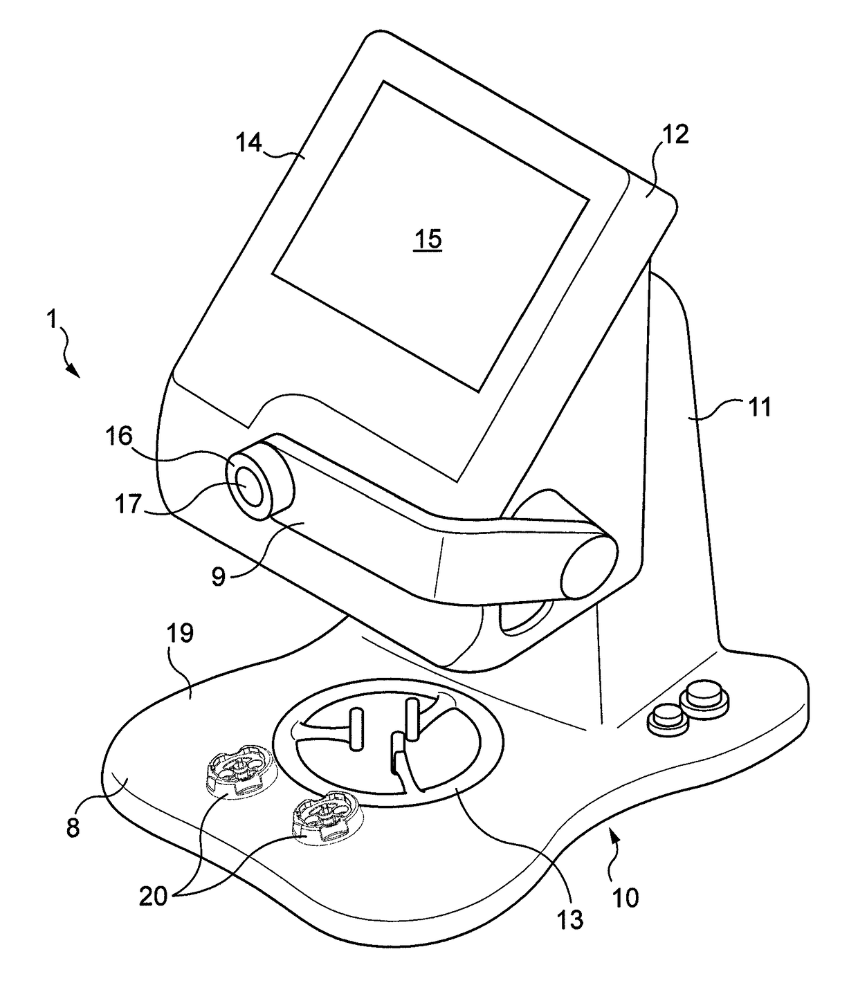
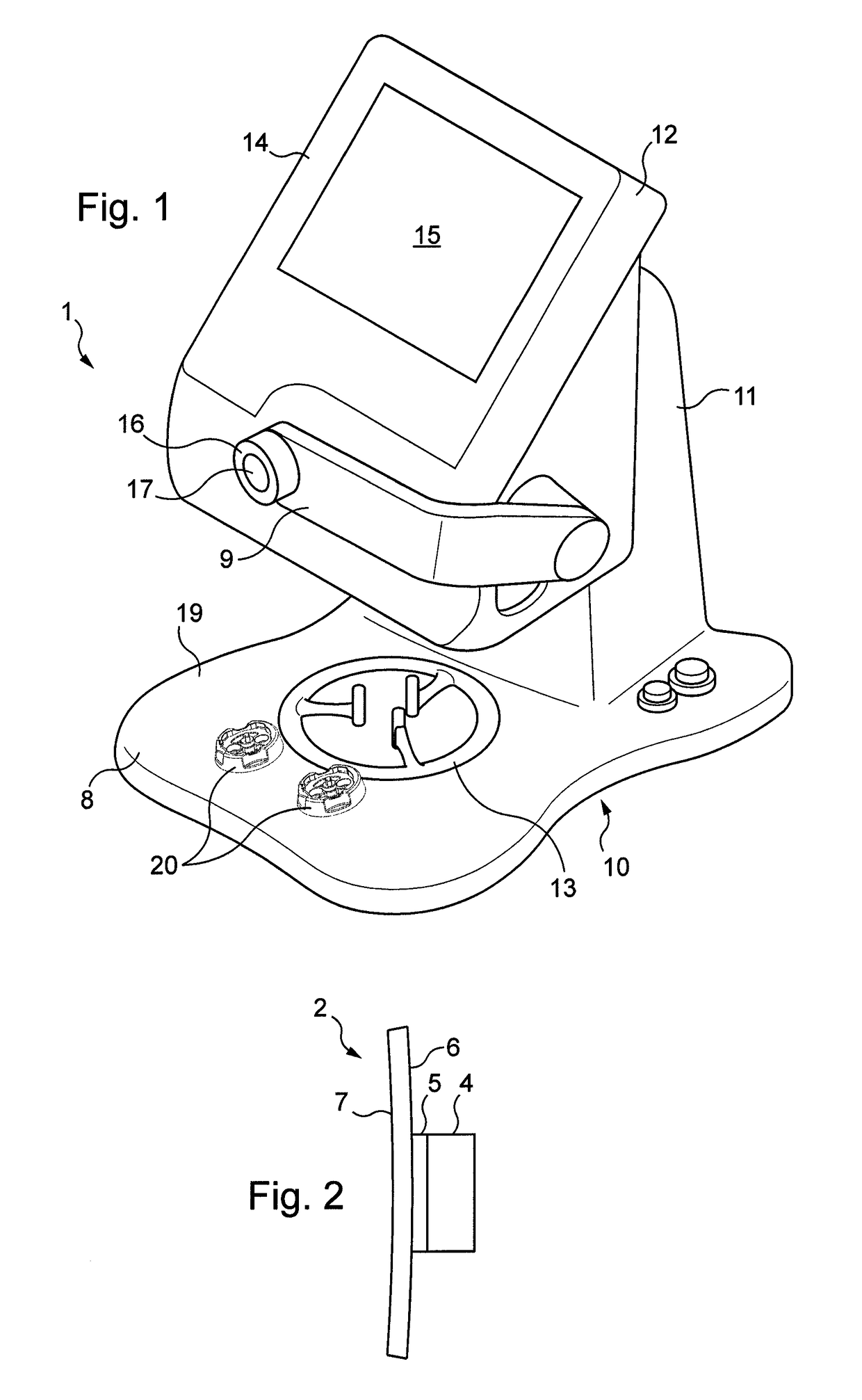
[0058]FIG. 1 illustrates a machine 1 for positioning an ophthalmic lens 2 on and attaching it to a positioning and centering pin 4 by way of an attachment member 5 (visible in FIG. 2) previously positioned on and attached to the positioning and centering pin 4.

[0059]FIG. 2 illustrates the ophthalmic lens 2 attached to the positioning and centering pin 4 by virtue of the attachment member 5.

[0060]The ophthalmic lens 2 has a front face 6 and a rear face 7.

[0061]The attachment member 5 is a substantially elastic adhesive pad which is fixed to the front face 6 of the lens 2.

[0062]The positioning and centering pin 4 is made of plastics material molded in one piece.

[0063]The machine 1 is a machine substantially similar to the machines of which the configuration and operation are described in the European patent applications EP 1 393 036, EP 2 139 642 and EP 1 919 663.

[0064]The machine 1 has a base 10, a stand 11 rising from the base 10 and a monitor 12 overhanging the base 10.

[0065]The ba...


PUM

PropertyMeasurementUnit
Fractionaaaaaaaaaa
Timeaaaaaaaaaa

Abstract

A system includes a positioning and centering pin (4) configured to be attached to an ophthalmic lens, an attachment member (5) configured to be positioned on and attached to the pin and to be attached to the lens, a tool (20) for positioning the attachment member on the pin, and which includes a body (42) provided with at least one receiving recess configured to at least partially receive at least one of the attachment members and the pin, at least one centering member (48, 56) and at least one guide member (48, 57), which are configured such that, when the attachment member and the pin are mounted on the tool, the attachment member is centered relative to the body and the pin is guided relative to the body, whereby the attachment member is positioned in a predetermined position on the pin.

Description

BACKGROUND OF THE INVENTION[0001]Field of the Invention[0002]The invention relates to the general field of the positioning of attachment members on positioning and centering pins for ophthalmic lenses in order to subsequently attach these positioning and centering pins to these lenses, and the invention concerns in particular the systems comprising such a positioning and centering pin, such an attachment member and a tool for positioning the attachment member on the positioning and centering pin, and groups of such systems.[0003]The invention also relates to methods for positioning such attachment members on such positioning and centering pins.[0004]Description of the Related Art[0005]The invention also concerns machines for positioning ophthalmic lenses on and attaching them to such positioning and centering pins.[0006]It is known that ophthalmic lenses undergo various manufacturing steps. The manufacturing processes generally employed to obtain a finished lens trimmed to the shape...

Claims


Application Information

Patent Timeline
IPC IPC(8): B24B41/06B24B13/005B24B47/22B24B9/14
CPCB24B13/0055B24B9/14B24B13/005B24B47/225B24B9/146Y10T29/49998
Inventor BRECHEMIER, BERNARD
Owner ESSILOR INT CIE GEN DOPTIQUE
Why Eureka
Try Eureka