Printer for printing of printable objects and ink ribbon cassette for use in a printer

a printer and ink ribbon technology, applied in printing, typewriters, power drive mechanisms, etc., can solve the problems of effort associated with insertion of new ink ribbons, and achieve the effects of easy replacement, low effort, and reliably located in the given position

Active Publication Date: 2017-10-31
PHOENIX CONTACT GMBH & CO KG
View PDF14 Cites 2 Cited by
  • Summary
  • Abstract
  • Description
  • Claims
  • Application Information

AI Technical Summary

Benefits of technology

[0013]Therefore the object of this invention is to devise a printer as described initially for printing of printable objects for the identification of electrical components, in which the use of an ink ribbon is associated with little effort and at the same time it is ensured that in print operation the ink ribbon has a given distance to the print head. Moreover an ink ribbon cassette is to be made available which makes it possible for the ink ribbon cassette to be reliably located in its given position within the printer with easy replaceability.
[0014]This object is achieved in the printer as claimed in the invention in that the print head holder on whose bottom the print head is attached is pivotably mounted in the housing such that in the closed position of the print head holder the print head is located in a working position above the ink ribbon of the ink ribbon cassette and in a swung-up position of the print head holder an ink ribbon cassette is inserted into the housing or can be removed from the housing. The arrangement of the print head on a print head holder which is pivotably mounted in the housing first of all makes it very easily possible to move the print head out of its working position into a second position in which the insertion of an ink ribbon cassette into the housing or the removal of the ink ribbon cassette from the housing is easily possible. If the print head holder is made stable enough, by the arrangement of the print head on the print head holder it is also ensured that the print head in its working position is always in the same position within the printer.
[0015]In the printer as claimed in the invention it is moreover provided that on the top of the ink ribbon cassette or on the bottom of the print head holder at least one spring arm is formed which is deflected in the closed position of the print head holder such that the ink ribbon cassette has a given distance to the print head. By forming at least one spring arm on the top of the ink ribbon cassette or on the bottom of the print head holder, production-dictated differences in the dimensions of the individual replaceable ink ribbon cassettes are thus equalized so that overly great demands are not imposed on the individual ink ribbon cassettes with respect to their dimensions. Since by the formation at least one spring arm the distance between the free end of the print head and the ink ribbon moves within a certain tolerance range, it is easily ensured that an exact ink impression and high print quality can be achieved.

Problems solved by technology

Altogether the insertion of a new ink ribbon is thus associated with effort, and it must be watched that the ink ribbon is properly routed past the print head and attached to the take-up spool.

Method used


Image

  • Printer for printing of printable objects and ink ribbon cassette for use in a printer
  • Printer for printing of printable objects and ink ribbon cassette for use in a printer
  • Printer for printing of printable objects and ink ribbon cassette for use in a printer

Examples


Embodiment Construction

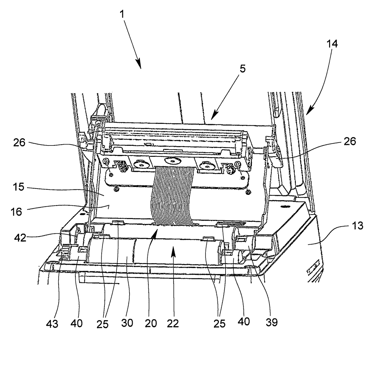
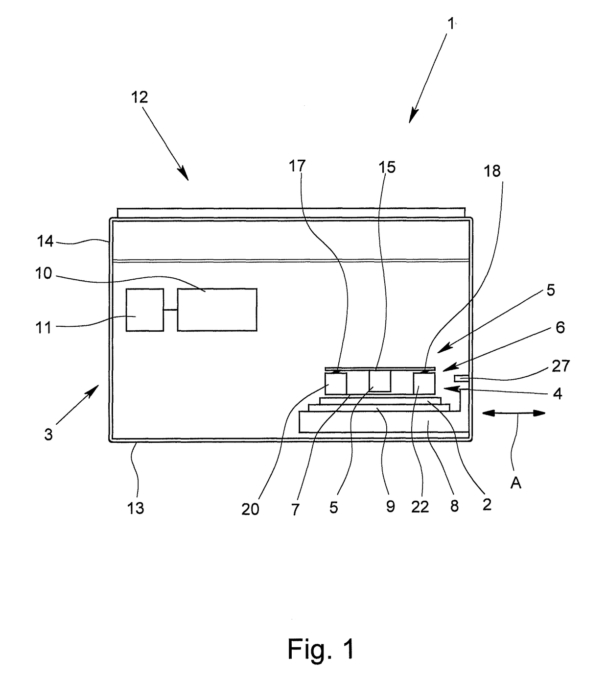
[0035]FIG. 1 shows a printer 1 according to this invention in a highly simplified schematic in a longitudinal section. The printer 1 which is preferably a thermotransfer printer is used to print printable objects 2, in particular in card format or in the form of carrier sheets. The printer 1 has a housing 3 in which a print space 4 is formed. Moreover in the housing 3 there are a print head 5 and an ink ribbon cassette 6 whose ink ribbon 7 in the print process is located a very short distance above the printable object 2 which is to be printed. A receiving device 8 which is made in the manner of a drawer or a transport carriage can be moved between a loading and unloading position outside the print space 4 and a print position within the print space 4. In FIG. 1 the direction of movement of the receiving device 8 runs in the direction of arrow A, in the representation according to FIG. 1 the receiving device 8 being located within the print space 4, therefore in the print position. ...


PUM


Abstract

A printer includes: a housing, a print space within the housing, a print head, a replaceable ink ribbon cassette, a receiving device for a printable object which is to be printed, a control and evaluation unit, and an input and display apparatus. The receiving device can travel between a loading and unloading position outside the print space and a print position within the print space.A print head holder on whose bottom the print head is attached is pivotably mounted in the housing. In the closed position of the print head holder the print head is located in a working position above the ink ribbon cassette. In a swung-up position of the print head holder an ink ribbon cassette can be inserted into the housing or can be removed from the housing. At least one spring arm is formed on the top of the ink ribbon cassette or on the bottom of the print head holder.

Description

BACKGROUND OF THE INVENTION[0001]Field of the Invention[0002]The invention relates to a printer for printing of printable objects for identification of electrical components, with a housing, with a print space which is made within the housing, with a print head, with a replaceable ink ribbon cassette which has an ink ribbon, with a receiving device for a printable object which is to be printed, with a control and evaluation unit and with an input and display apparatus, and the receiving device can travel between a loading and unloading position outside the print space and a print position within the print space.[0003]Description of Related Art[0004]In industrial and commercial practice, for marking and labeling of machinery, devices, terminals, cables or leads, different types of marking and identification labels are used on which information is applied relating to the components to which they are assigned. To do this the marking and identification labels in a printer are provided w...

Claims


Application Information

Patent Timeline
Patent Type & Authority Patents(United States)
IPC IPC(8): B41J32/00B41J25/304B41J2/325
CPCB41J2/325B41J32/00B41J25/304B41J3/407B41J17/32
Inventor KLOCKE, SANDRAKLAGES, KILIANSCHIERHOLZ, ALBRECHT
Owner PHOENIX CONTACT GMBH & CO KG
Why Eureka
Try Eureka