Ferromagnetic fastener locating device

a technology of ferromagnetic fasteners and locating devices, which is applied in the field of hand tools, can solve problems such as inability to reliably locate ferromagnetic objects, device may still give the user a false indication, and may cause erroneous results

Active Publication Date: 2019-02-05
DIAMOND RESOURCE
View PDF12 Cites 3 Cited by
  • Summary
  • Abstract
  • Description
  • Claims
  • Application Information

AI Technical Summary

Benefits of technology

[0012]Therefore, what is needed is a device for locating ferromagnetic objects that eliminates the need to calibrate the device for wall density before each use and a device that more reliably indicates the location of a ferromagnetic object.
[0029]In another embodiment, the device has at least one sloping surface extending along an interior wall of the housing and spiraling forward towards the front surface. The magnet assembly has at least one protrusion or leg to engage the sloping surface(s), thereby causing the magnet assembly to rotate about the longitudinal central axis as it moves between the resting position and the active position.

Problems solved by technology

A problem with electronic locating devices is the inherent unreliability caused by variables such as the location where the device is calibrated.
This is so because the user generally has no way to know the correct location on the wall to calibrate the device since the user does not know the location of structural members within the wall.
Even if the device is somehow calibrated at an ideal low-density location on the wall, the device still may give the user a false indication if it detects an increase in wall density that is due to something other than a support member.
Erroneous results may occur if the device detects something such as a pipe, insulation, or simply a change in density of the wall covering itself.
One problem with some magnetic stud sensors is that the method of indication may falsely indicate the location of a stud.
If such a device is used on a textured wall, the indicator may move out of its resting position as a result of vibration as the device passes over the textured surface.

Method used


Image

  • Ferromagnetic fastener locating device
  • Ferromagnetic fastener locating device
  • Ferromagnetic fastener locating device

Examples


Embodiment Construction

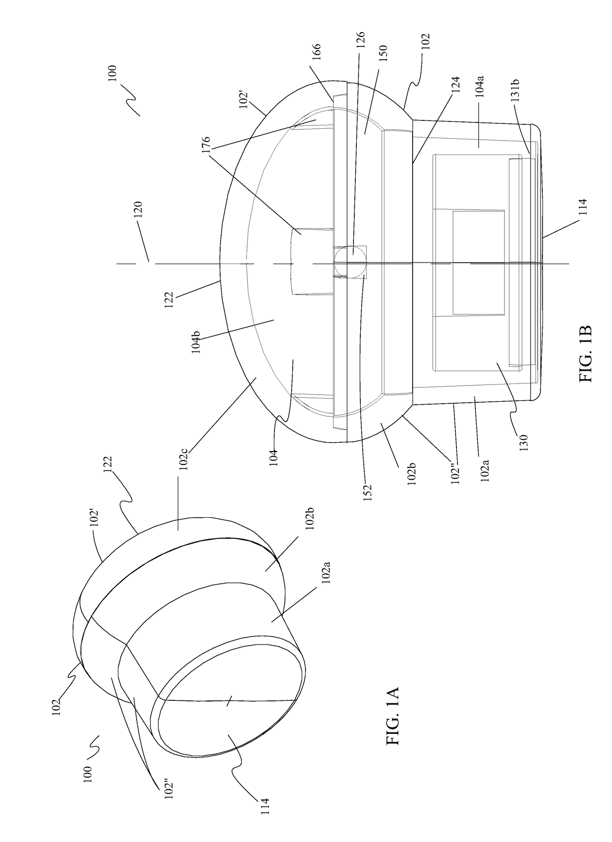
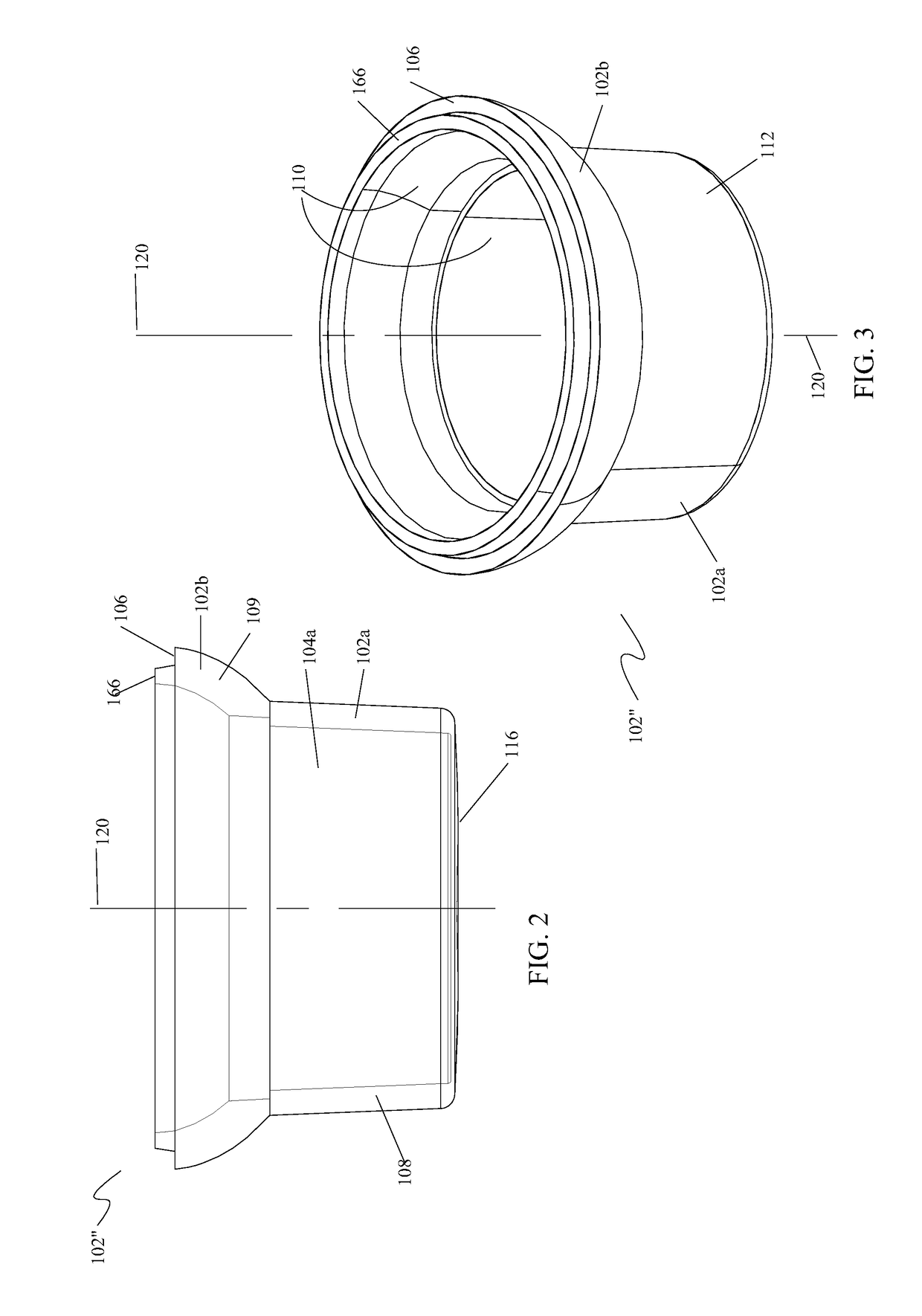
[0050]The preferred embodiments of the present invention are illustrated in FIGS. 1-12. FIG. 1A is a front perspective view of one embodiment of the present invention showing a device 100 for locating a ferromagnetic material. Device 100 includes a housing 102 having an upper housing 102′, a lower housing 102″, a front end 114, and a rear end or surface 122. Lower housing 102″ has a cup portion 102a, a bowl portion 102b, a perimeter wall 108, and a front planar surface 116. Upper housing 102′ has a dome portion 102c forming a rear cap for housing 102″. Housing 102 is made of a non-magnetic material such as acrylic, acrylonitrile butadiene styrene (ABS) plastic, polyvinyl chloride (PVC), natural nylon, polycarbonate, other plastics, and non-magnetic metals. Preferably, housing 102 is made of an optically clear acrylic.

[0051]Turning now to FIG. 1B, there is illustrated a cross-sectional view of device 100 showing the various internal components of the preferred embodiment. Housing 102...


PUM


Abstract

For locating a ferromagnetic object, a device has a non-magnetic housing with a perimeter wall, a front surface, and a rear surface. The perimeter wall defines a chamber within the housing. A stop element is located within the chamber between the front surface and the rear surface. A magnet element is housed within the chamber and is movable between a resting position, where the magnet element is proximate the stop element, and an active position, where the magnet element is proximate the front surface. The device has a mechanism for returning the magnet element to the resting position in the absence of a ferromagnetic object located proximate the front end of the device.

Description

[0001]This application claims the benefit of U.S. Provisional Patent Application No. 61 / 419,286, filed Dec. 3, 2010.BACKGROUND OF THE INVENTION1. Field of the Invention[0002]The present invention relates generally to hand tools. More specifically, the present invention relates to a device for locating ferromagnetic objects.2. Description of the Prior Art[0003]It is often necessary to locate structural support members that are hidden behind a wall, ceiling, or floor covering material. These support members include wall studs, floor joists, beams, roof rafters, and strapping. The support members may be wood, as are commonly used in residential construction, or metal, as are commonly used in commercial construction.[0004]Wall or ceiling coverings are secured to structural support members using ferromagnetic fasteners such as screws or nails that are driven through the covering and into the supporting members underneath. For example, drywall sheets are secured with fasteners to framing ...

Claims


Application Information

Patent Timeline
Patent Type & Authority Patents(United States)
IPC IPC(8): G01R33/02G01V3/08G01R19/00
CPCG01V3/08G01R33/02G01V3/081G01V3/165
Inventor BLAKE, JOHN
Owner DIAMOND RESOURCE
Why Eureka
Try Eureka