Attachment structure of an aircraft

a technology of aircraft and attachment structure, which is applied in the field of attachment structure of aircraft, can solve the problems of increasing the weight of the aircraft and needing additional space, and achieve the effect of easy tailoring and/or reconstruction of the interior

Active Publication Date: 2017-11-07
AIRBUS OPERATIONS GMBH
View PDF34 Cites 1 Cited by
  • Summary
  • Abstract
  • Description
  • Claims
  • Application Information

AI Technical Summary

Benefits of technology

[0008]The attachment structure may be used for saving weight, saving space and / or to have a better integration of moving or fast removable equipment units, cabin elements and equipment (such as trolleys) directly to the primary structure.
[0015]In general, the tooth profile may have protrusions or indentations in a direction orthogonal to the longitudinal direction. For example, the tooth profile may be a saw tooth profile. Also the second engagement element may have a saw tooth profile, which also may provide adjustability of the attachment structure in the longitudinal direction.
[0016]According to an embodiment of the invention, the first engagement element and the second engagement element form a lock mechanism adapted for unlocking, when moving the second attachment device away from the first attachment device. The two profiles of the first and second engagement element may provide a contact in closed position (for example by direct securing by form closure). The two engagement elements may provide a quick attach / release mechanism for an easy tailoring and / or reconstruction of the interior of the aircraft.
[0021]According to an embodiment of the invention, the second attachment device is attached to the movable bin, such that the second engagement element engages the first engagement (in particular only) in the closed position. The crash loads may only have to be ensured by a closed bin. To certify a bin, it may be only necessary to calculate the crash load in standard (closed) position. In turbulences during flight or starting / landing operations, the movable bin has to be closed. With the second attachment device directly fixed to the movable bin and the first attachment device directly fixed on the primary structure, the robustness against high loads may be ensured in the closed position.
[0026]According to an embodiment of the invention, the movable bin is mounted to the outer structure with bearings adapted for floating in the longitudinal direction. Since nearly most of a load in longitudinal direction is transferred via the attachment structure. The bearings (such as pivotal bearings, rails, tracks) do not have to transfer high loads in longitudinal direction and may be more lightweight and / or smaller. In particular, it is not necessary that the bearings are supported in longitudinal direction.

Problems solved by technology

Furthermore, considering a movable bin, loads on the movable bin and on the baggage inside and a possible crash load factor of 9 g forward usually cannot directly transfer into the primary structure, but have to be transferred via bearings used for moving the bin during opening and closing.
However, such a tie rod may need additional space and may add to the weight of the aircraft.

Method used


Image

  • Attachment structure of an aircraft
  • Attachment structure of an aircraft
  • Attachment structure of an aircraft

Examples


Embodiment Construction

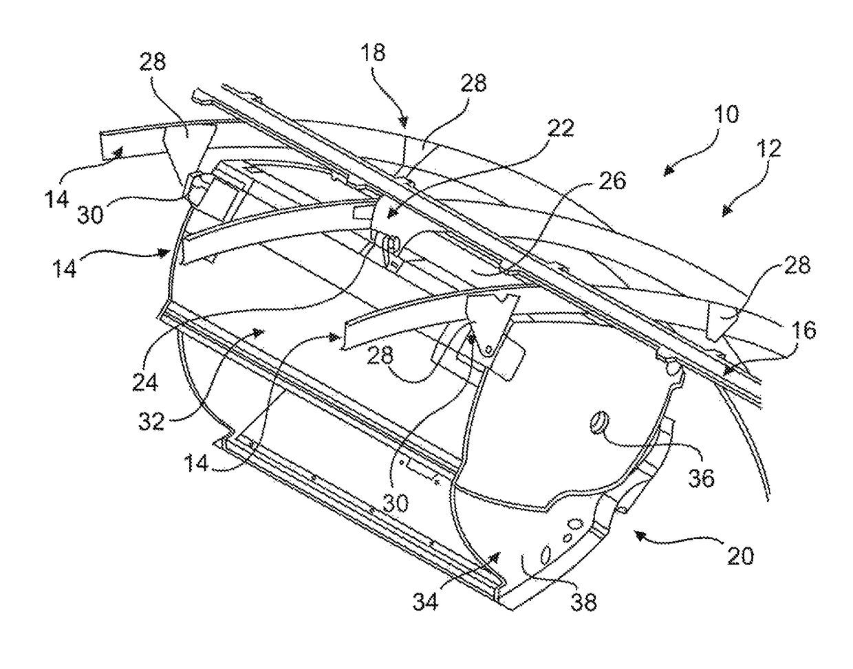
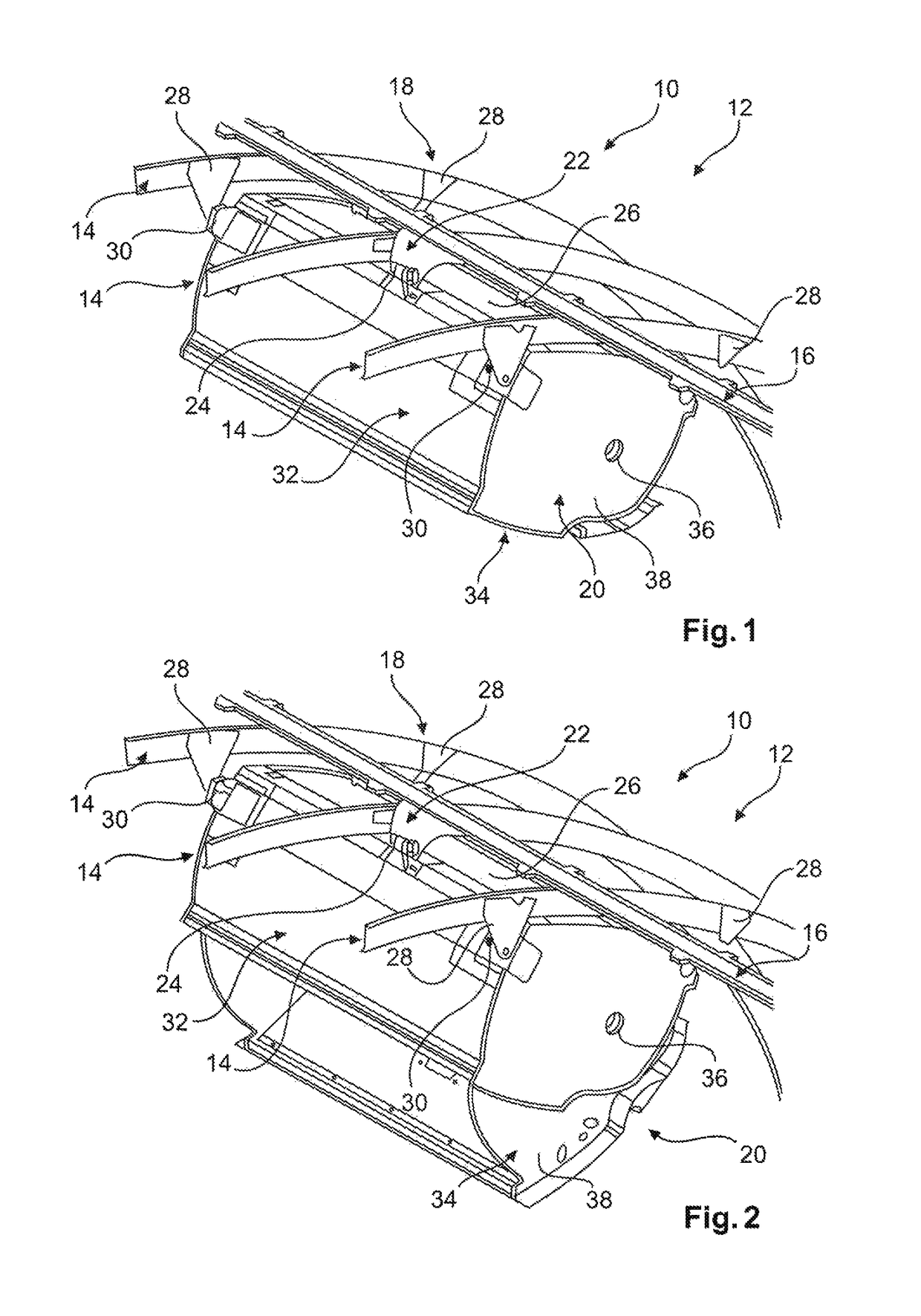
[0046]FIG. 1 shows the primary structure 10 of an aircraft 12 comprising frames 14 surrounding the fuselage of the aircraft 12 and comprising stringers 16 that extend in a longitudinal direction over the frames 14. The frames 14 are usually rings surrounding the fuselage of the aircraft 12.

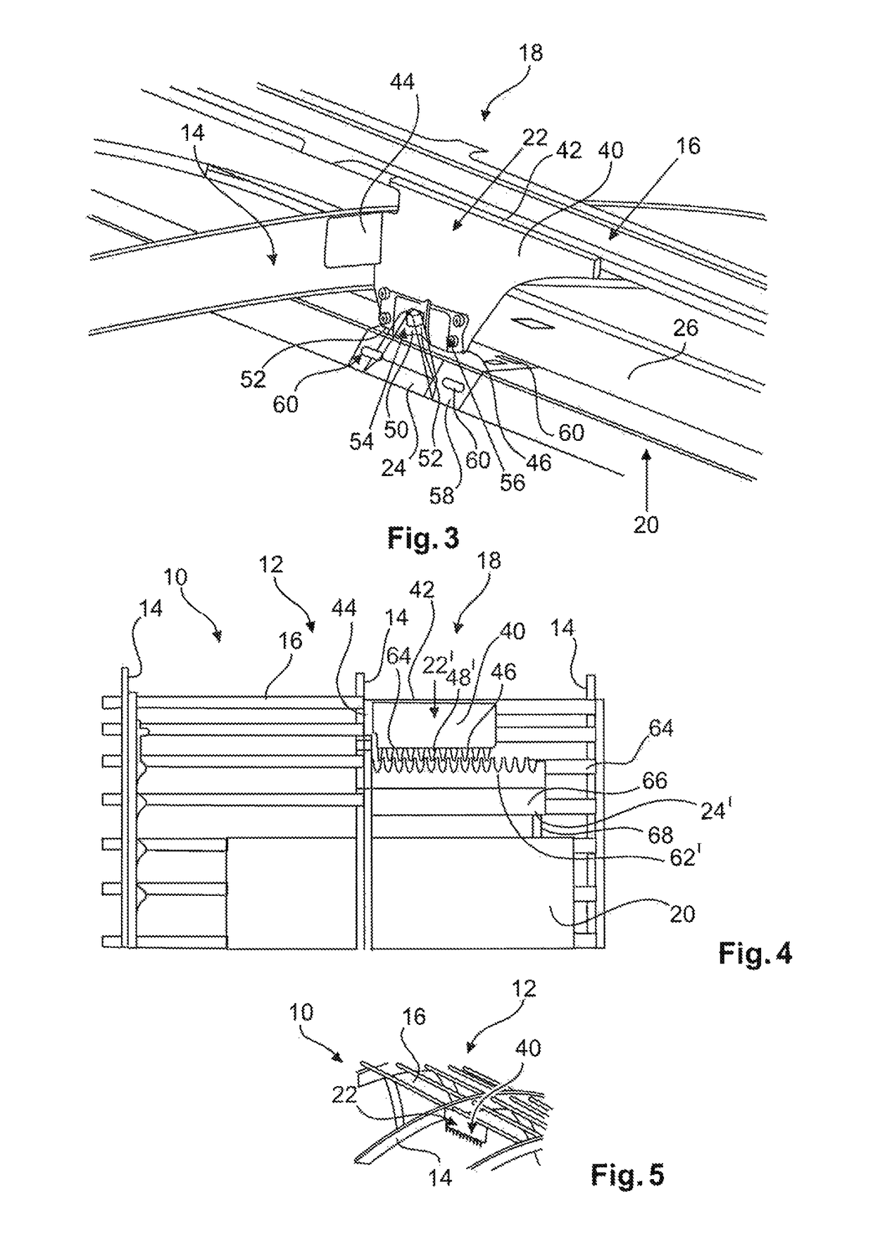
[0047]Furthermore, FIG. 1 shows an attachment structure 18 that directly connects an equipment unit 20 to the primary structure 10. The attachment structure 18 comprises a first attachment device 22 that is attached to a frame 14 and a stringer 16 at a crossing point of the frame 14 and the stringer 16, and a second attachment device 24 that is attached to a back or rear wall 26 of the equipment unit 20. Most of the force acting on the equipment unit in longitudinal direction is directly transferred by the second attachment device 24 to the first attachment device 22 engaged in the second attachment device 24 and then directly transferred into the primary structure 10.

[0048]The equipment unit 20 i...


PUM

PropertyMeasurementUnit
forceaaaaaaaaaa
dampingaaaaaaaaaa
attachment structureaaaaaaaaaa

Abstract

An attachment structure for an equipment unit of an aircraft includes a first attachment device extending in a longitudinal direction of the aircraft, wherein the first attachment device is attached to a stringer and to a frame and wherein the first attachment device has a first engagement element and a second attachment device attachable to the equipment unit, wherein the second attachment device has a second engagement element adapted for engaging into the first engagement element, such that a force from the equipment unit in the longitudinal direction on the second attachment device is transferred via the second engagement element to the first engagement element and via the first attachment device to the stringer and the frame.

Description

FIELD OF THE INVENTION[0001]The invention relates to an attachment structure of an aircraft and a method for attaching an equipment unit to a primary structure of an aircraft.BACKGROUND OF THE INVENTION[0002]In an aircraft, equipment units like monuments, galleys, cupboards, toilets, hat racks, etc. are usually connected to the primary structure of the aircraft to prevent moving of the equipment unit during phases of acceleration and deceleration. An important situation relates to very strong phases in the x-direction (longitudinal direction) of the aircraft, which, for example, may develop in a crash situation. According to current standards, the attachment of an equipment unit to the aircraft has to withstand an acceleration of up to 9 g (1 g=standard gravitational acceleration on earth).[0003]Furthermore, considering a movable bin, loads on the movable bin and on the baggage inside and a possible crash load factor of 9 g forward usually cannot directly transfer into the primary s...

Claims


Application Information

Patent Timeline
Patent Type & Authority Patents(United States)
IPC IPC(8): B64C1/06F16B1/02B64C1/00B64D11/00
CPCF16B1/02B64C1/00B64D11/003Y10T29/49826Y02T50/46Y02T50/40
Inventor SCHNEIDER, UWEBIELIK, PETERMARGOV, HRISTOKOTIAN, RAJ
Owner AIRBUS OPERATIONS GMBH
Why Eureka
Try Eureka