Angle-resolving radar sensor

a radar sensor and angle resolution technology, applied in direction finders using radio waves, instruments, reradiation, etc., can solve the problems of corresponding differences and high hardware costs, and achieve the effects of small aperture, high angular resolution, and reduced hardware costs

Active Publication Date: 2017-11-07
ROBERT BOSCH GMBH
View PDF25 Cites 2 Cited by
  • Summary
  • Abstract
  • Description
  • Claims
  • Application Information

AI Technical Summary

Benefits of technology

[0008]A selection of antenna elements in which each individual element is connected to one of the receive channels is to be referred to in the following as an “array.” The switching device may be used, for example, for switching between an array having a great aperture and an array having a smaller aperture. The array having a great aperture provides ambiguous angle information having a high angular resolution. The array having the smaller aperture and correspondingly smaller distances between the adjacent antenna elements may then be used to eliminate the ambiguities. Likewise, it is also possible to switch between three or more different arrays in a regular sequence. The arrays do not necessarily have to have different apertures in this case. For example, it is also possible to select different arrays having identical apertures in which the distances between the individual antenna elements are selected in such a way that the phase relations obtained for the different arrays are only consistent for one single angle of incidence, thus eliminating the ambiguity.

Problems solved by technology

These running time differences result in corresponding differences in the phase of the signals which are received by the antenna elements and evaluated in the associated evaluation channels.
In this case, however, the number of antenna elements and thus the number of necessary evaluation channels increases with increasing aperture, so that high hardware costs arise accordingly.

Method used


Image

  • Angle-resolving radar sensor
  • Angle-resolving radar sensor
  • Angle-resolving radar sensor

Examples


Embodiment Construction

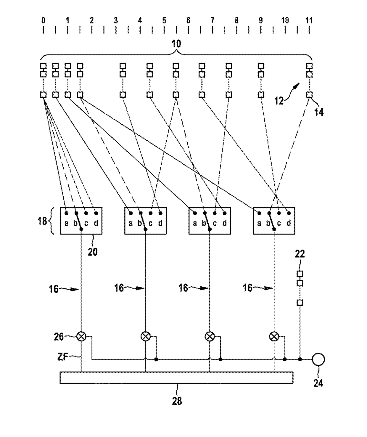
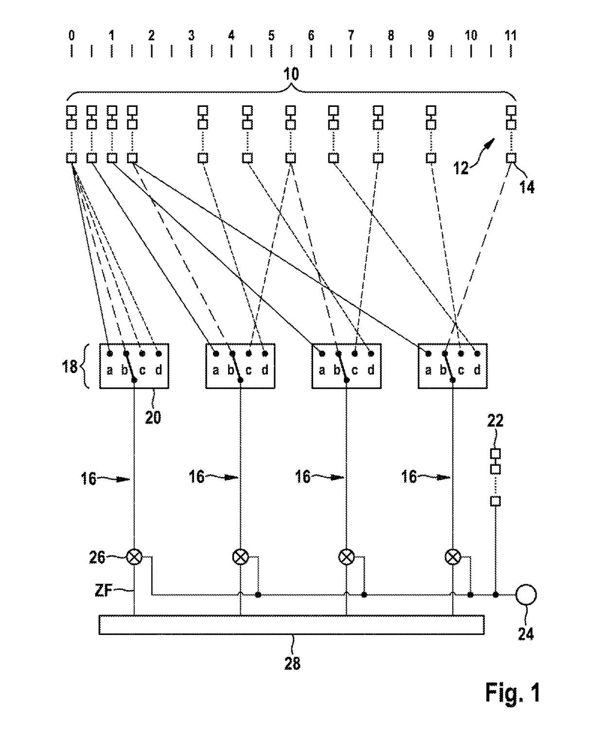
[0012]The radar sensor shown in FIG. 1 has a planar group antenna 10 which is formed in the illustrated example by eleven antenna elements 12 which are situated horizontally next to one another. Each antenna element 12 includes multiple patches 14 which are situated in a vertical gap, fed in series, and together cause a beam formation in the vertical direction (elevation).

[0013]While in a conventional radar sensor a separate evaluation channel is assigned to each individual antenna element, the radar sensor described here only has a total of four evaluation channels 16 for evaluating the signals of a total of eleven antenna elements 12. A switching device 18 is formed by four electronic switches 20, each of which is associated with one of the evaluation channels 16 and has four different switching positions. Evaluation channel 16 is connected to one of antenna elements 12 in each switching position. In this way, a different selection of four antenna elements, whose signals are evalu...


PUM


Abstract

An angle-resolving radar sensor, e.g., for motor vehicles, includes; an antenna having multiple antenna elements which are each switchable to one of multiple evaluation channels; and an evaluation device for determining the angle of incidence of a received signal based on the amplitudes measured in the evaluation channels. The number of antenna elements is greater than the number of evaluation channels and a switching device is provided to connect the evaluation channels alternatingly to different selections of antenna elements.

Description

BACKGROUND OF THE INVENTION[0001]1. Field of the Invention[0002]The present invention relates to an angle-resolving radar sensor, in particular for motor vehicles, including an antenna having multiple antenna elements which are each switchable to one of multiple evaluation channels and including an evaluation device for determining the angle of incidence of a received signal based on the amplitudes measured in the evaluation channels.[0003]2. Description of the Related Art[0004]Radar sensors are used in motor vehicles, for example, to measure distances, relative velocities, and azimuths of vehicles or other objects located ahead of one's own vehicle. Radar sensors including a group antenna having a planar design have the advantage in these applications that they only require little installation space. Individual antenna elements of the group antenna are situated at a distance from one another horizontally, so that different azimuths of the located objects result in different running...

Claims


Application Information

Patent Timeline
Patent Type & Authority Patents(United States)
IPC IPC(8): G01S3/16H01Q25/00H01Q1/32G01S13/02G01S13/34G01S7/02G01S3/22H01Q3/24
CPCG01S7/02G01S3/16G01S3/22G01S13/02H01Q1/3233H01Q3/24H01Q25/002G01S13/34G01S13/343
Inventor GROSS, VOLKERSCHOOR, MICHAEL
Owner ROBERT BOSCH GMBH
Why Eureka
Try Eureka