Graphical user interface systems and methods for data integration with data-driven engineering drawings

a technology of engineering drawings and user interfaces, applied in the direction of structured data retrieval, instruments, computing, etc., can solve the problems of limited use and application of detailed schematics, and limited how plant schematics have been traditionally utilized, and achieve the effect of limited data object orientation

Active Publication Date: 2017-11-07
ENVIRONMENTAL INTELLECT INC
View PDF20 Cites 3 Cited by
  • Summary
  • Abstract
  • Description
  • Claims
  • Application Information

AI Technical Summary

Benefits of technology

[0008]Described is a system and methodology, in which operating facility information is presented, exchanged, and updated within data-driven schematics and data management systems. The integration of plant data management systems with data-driven schematics, such as piping and instrumentation diagram (P&ID), process flow diagrams (PFDs) and isometric drawings, is an innovation that provides numerous benefits to multiple plant disciplines, including but not limited to Engineering, Operations, Maintenance, Instrumentation and Electrical, Procurement, Environmental, Safety, Industrial Hygiene, and Management personnel. In addition to data exchange, the system is capable of generating alerts when inequivalent properties are detected for objects in a relational database of a data-driven schematic and at least one data management system.

Problems solved by technology

However, plant schematics in their common, present-day format (e.g., AutoCAD® or Microstation®) have limited data object orientation; thus, detailed schematics have been limited in their use and application because there are inherent limitations to import and export data from plant schematics in their common, present-day format.
For this reason, plant schematics have offered plant personnel little more than a visual representation of a process akin to a digital photograph, which has limited how plant schematics have been traditionally utilized.

Method used


Image

  • Graphical user interface systems and methods for data integration with data-driven engineering drawings
  • Graphical user interface systems and methods for data integration with data-driven engineering drawings
  • Graphical user interface systems and methods for data integration with data-driven engineering drawings

Examples


Embodiment Construction

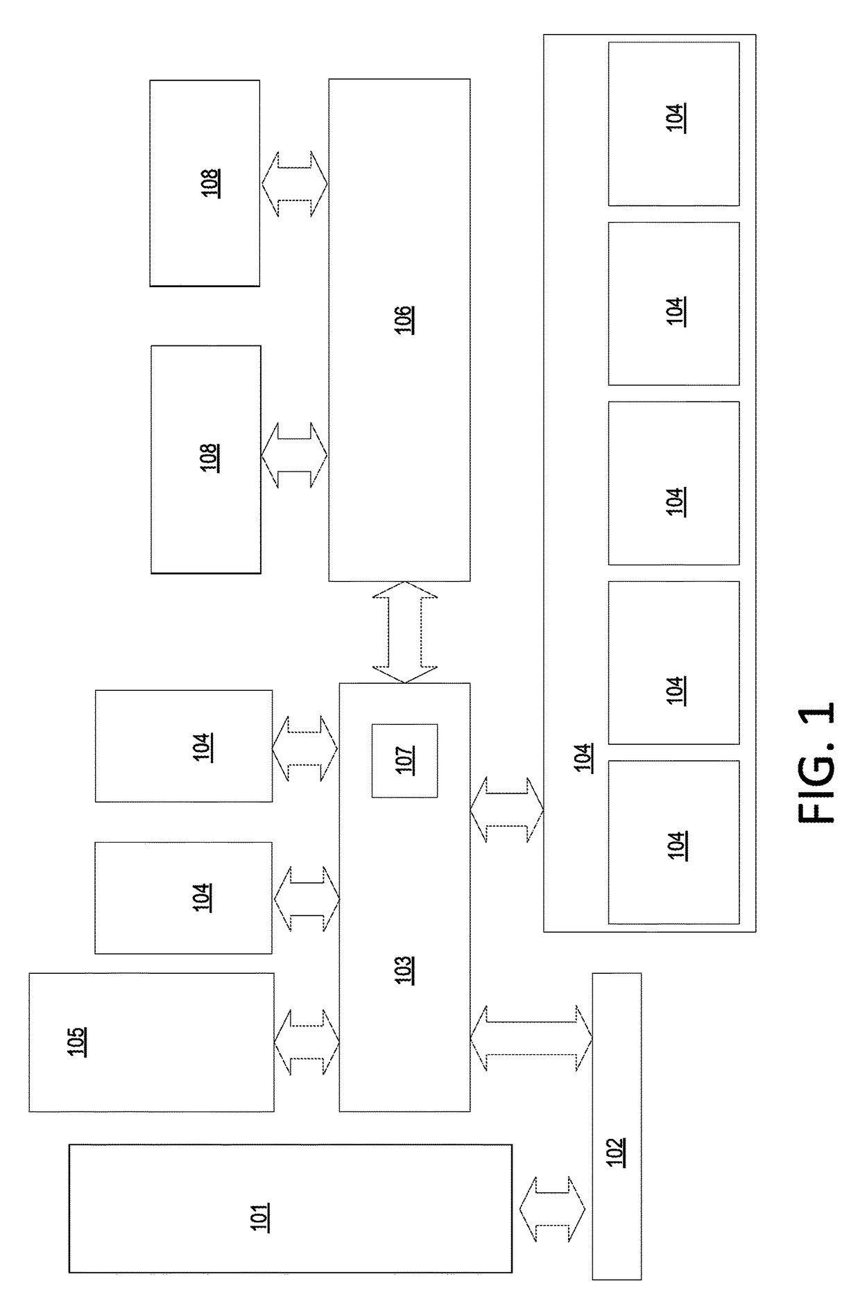
[0020]Described methods and systems apply to operating plants in a number of industries, including but not limited to energy, manufacturing, and processing, where facility schematics have been developed to either design, construct, and / or maintain the equipment comprising the operating plant. Computer Aided Design (CAD) and drafting tools are used by architects, engineers, and designers to create precision models, schematics, and technical illustrations.

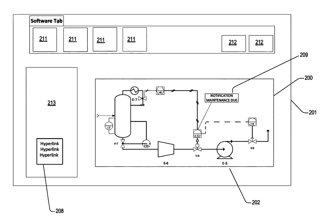
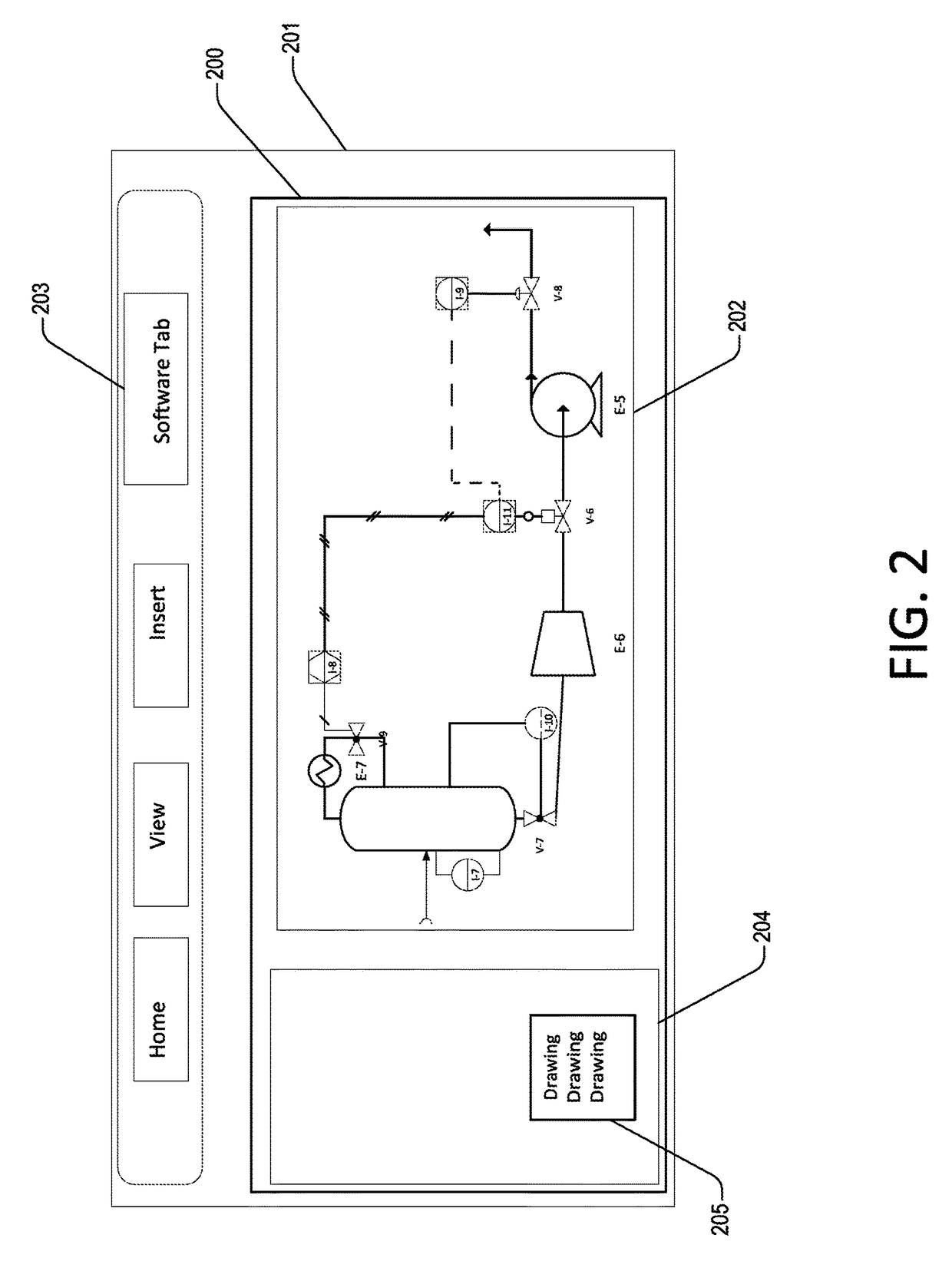
[0021]Schematics refer to facility diagrams, including but not limited to Piping and Instrumentation Diagrams (P&IDs), Process Flow Diagrams (PFDs), or isometric drawings, which represent a plurality of physical objects (pipes, vessels, equipment, etc.) within a commercial manufacturing operation. A data-driven schematic further includes a relational database in a native format within the architecture of the CAD environment to associate and store characteristics of the plurality of objects.

[0022]Data-driven schematics are commonly re...


PUM


Abstract

Described is a system and methodology, in which information is exchanged and / or updated within data-driven engineering schematics and various data management systems within an operating facility. The integration of plant data management systems with data-driven engineering schematics, such as piping and instrumentation diagram (P&ID), process flow diagrams (PFDs) and isometric drawings is an innovation that provides numerous benefits to multiple plant disciplines, including but not limited to Engineering, Operations, Maintenance, Procurement, Environmental, and Safety personnel. In addition to data exchange, described methods and systems within the graphical user interface are capable of generating alerts and initiating to changes to resolve data inconsistencies for a particular component represented in two or more data systems.

Description

CROSS-REFERENCE TO RELATED APPLICATIONS[0001]This application claims the benefit of application Ser. No. 62 / 054,194, filed Sep. 23, 2014, and application Ser. No. 62 / 101,689, filed Jan. 9, 2015, both of which are herein incorporated by reference in the entirety.BACKGROUND[0002]Operating facilities have a need for a system and process for exchanging and updating data and relationships within data-driven schematics and various data management systems within an operating facility. There is a need for integration of plant data management systems with data-driven schematics, such as piping and instrumentation diagram (P&ID), process flow diagrams (PFDs) and isometric drawings. A graphical user interface to support such plant data management is particularly challenging, as numerous plant disciplines are involved and are accustomed to applications that are customized to meet specific, disciplinary needs.[0003]Historically, plant operations have been separated into several professional disc...

Claims


Application Information

Patent Timeline
Patent Type & Authority Patents(United States)
IPC IPC(8): G06F3/048G06F3/0484G06F17/30
CPCG06F17/30557G06F3/04842G06F16/25
Inventor KLING, SHANE EDWARDASKEY, JESS MICHAEL
Owner ENVIRONMENTAL INTELLECT INC
Why Eureka
Try Eureka