Object detector
a detector and object technology, applied in the field of objects detection, can solve the problems of not getting the detection result of the detector, more difficult to detect objects accurately, etc., and achieve the effect of easy disabling the detection function of the detector
- Summary
- Abstract
- Description
- Claims
- Application Information
AI Technical Summary
Benefits of technology
Problems solved by technology
Method used
Image
Examples
first embodiment
1. First Embodiment
[0036]
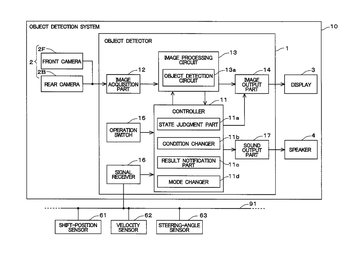
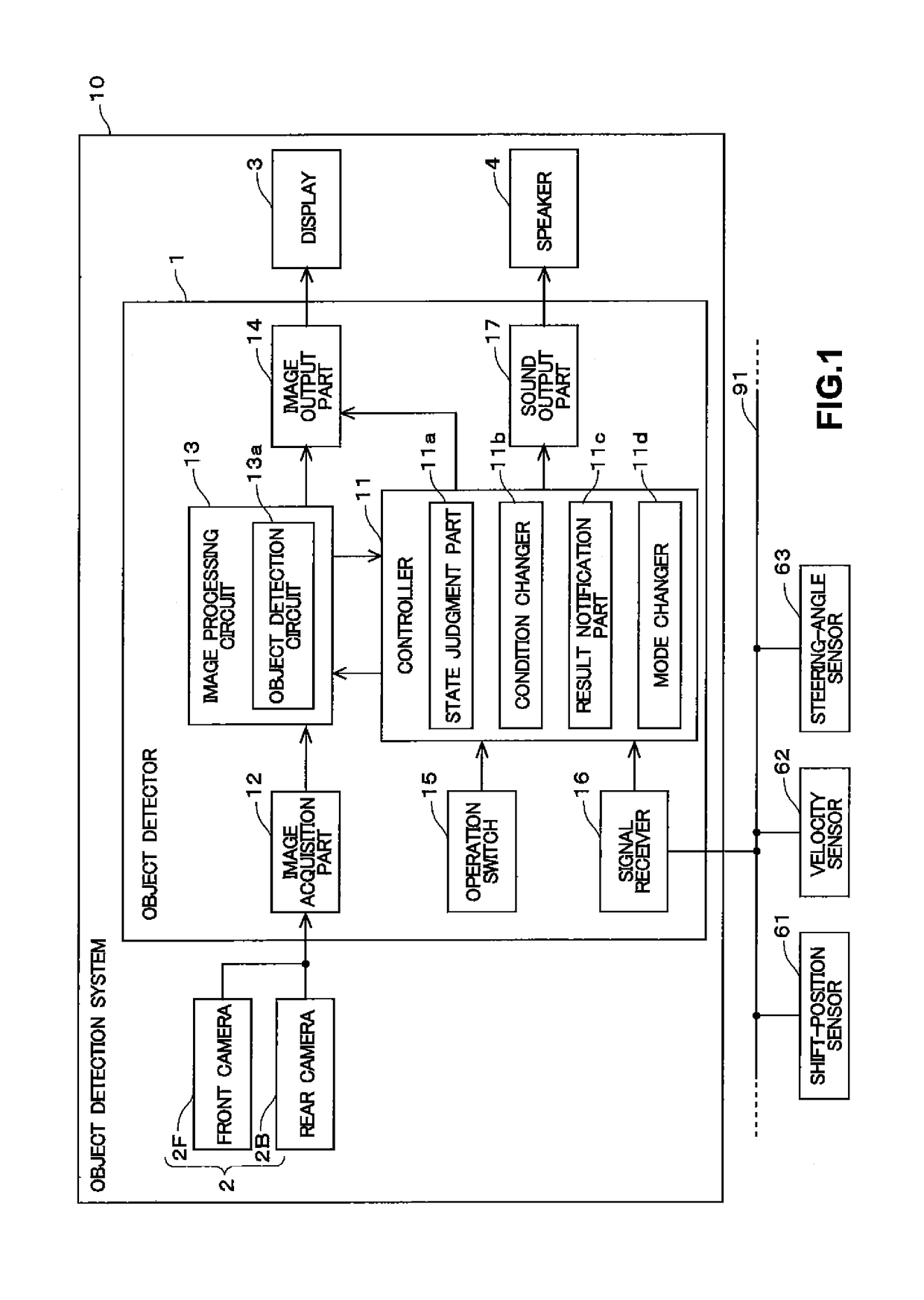
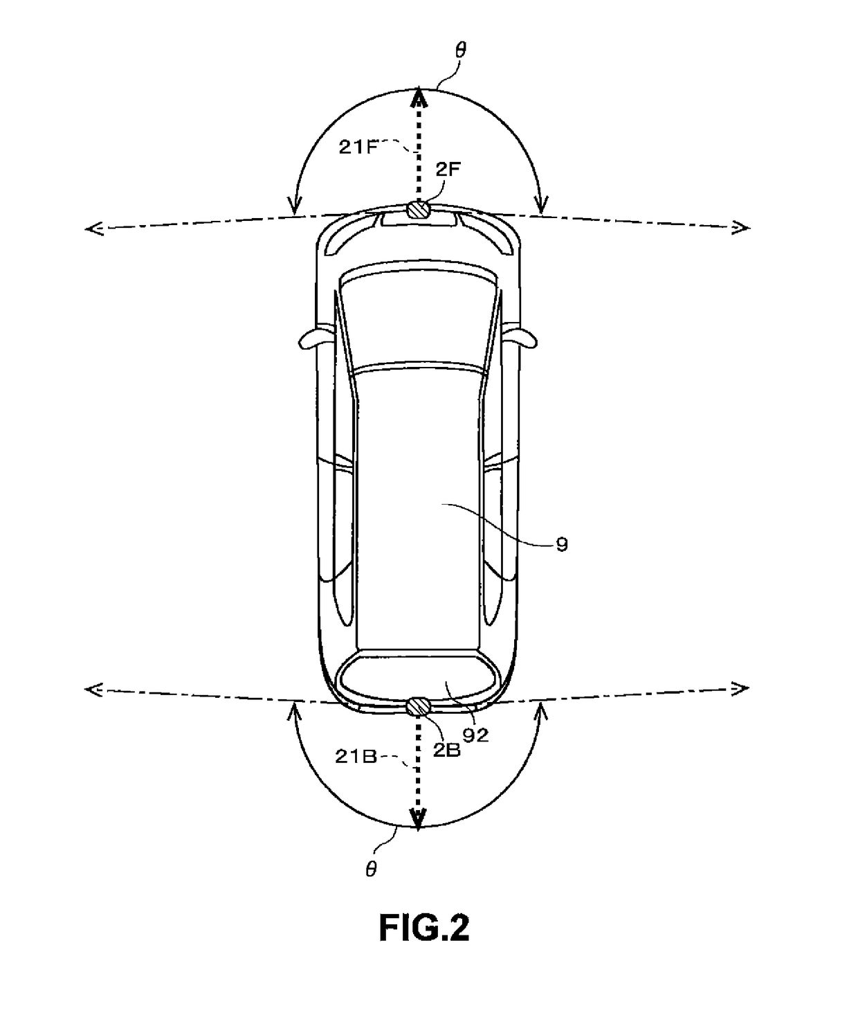
[0037]FIG. 1 shows a schematic configuration of an object detection system 10 of the embodiment. The object detection system 10 for installation in a vehicle such as a car has a function for detecting an object moving in the periphery of the vehicle, and then informing a user of the result of a detected object, if any. Hereafter, the vehicle equipped with the object detection system 10 is referred to as “own vehicle.”
[0038]The object detection system 10 includes a display 3 that displays a shot image and a speaker 4 that generates sound. The display 3 is located at a position that a user (primarily a driver) can see in a vehicle cabin of the own vehicle to inform the user of various types of information. The display 3 may have a navigation function for providing route guidance to a destination, and / or a touch panel function for receiving a user operation. The speaker 4 is located in the vehicle cabin of the own vehicle to inform the user of information with ...
second embodiment
2. Second Embodiment
[0115]Next, the second embodiment is described. The configuration and the processing on an object detection system 10 of the second embodiment are substantially the same as the ones of the first embodiment. Thus, the points different from the first embodiment are primarily described. On the first embodiment, the state judgment part 11a judges whether enabling the detection function of the object detection circuit 13a is acceptable or not, based on the velocity and the steering angle of the own vehicle 9. In the second embodiment, a state judgment part 11a judges whether enabling the detection function of an object detection circuit 13a is acceptable or not, in further consideration of the operation state of the anti-lock braking system of an own vehicle 9.
[0116]FIG. 14 shows a configuration of an object detection system 10 of the second embodiment. As shown in the figure, a signal receiver 16 of the second embodiment can receive a signal via an in-vehicle network...
third embodiment
3. Third Embodiment
[0122]Next, the third embodiment is described. The configuration and the processing on an object detection system 10 of the third embodiment are substantially the same as the ones of the first embodiment. Thus, the points different from the first embodiment are primarily described. On the first embodiment, the state judgment part 11a judges whether enabling the detection function of the object detection circuit 13a is acceptable or not based on the velocity and the steering angle of the own vehicle 9. On the third embodiment, a state judgment part 11a judges whether enabling the detection function of an object detection circuit 13a is acceptable or not, in further consideration of the open-close state of a rear door 92 in a back mode M3.
[0123]FIG. 15 shows the configuration of the object detection system 10 of the third embodiment. As shown in the figure, a signal receiver 16 of the third embodiment can receive a signal via an in-vehicle network 91 from a courtesy...
PUM
 Abstract
Description
Claims
Application Information
 - R&D
- Intellectual Property
- Life Sciences
- Materials
- Tech Scout
- Unparalleled Data Quality
- Higher Quality Content
- 60% Fewer Hallucinations
Browse by: Latest US Patents, China's latest patents, Technical Efficacy Thesaurus, Application Domain, Technology Topic, Popular Technical Reports.
© 2025 PatSnap. All rights reserved.Legal|Privacy policy|Modern Slavery Act Transparency Statement|Sitemap|About US| Contact US: help@patsnap.com


