
Monitoring apparatus and communication system

a technology of communication system and monitoring apparatus, applied in the field of monitoring apparatus, can solve the problems of large software size, unwarranted vulnerability to a sophisticated illegal attack, and the reception apparatus cannot determine whether the frame is valid or invalid, and achieve the effect of efficient disabling

Inactive Publication Date: 2017-09-21
HONDA MOTOR CO LTD
View PDF5 Cites 1 Cited by
  • Summary
  • Abstract
  • Description
  • Claims
  • Application Information

AI Technical Summary

Benefits of technology

The present invention is a monitoring apparatus that can detect invalid frames in an in-vehicle network and efficiently disable them using a simple method. The communication system provides a means to prevent the influence of these frames, thereby ensuring proper network functioning.

Problems solved by technology

The above conventional examples, however, have the following problems.
Thus, the ECUs need to establish communication in a state in which a plurality of identification IDs used for transmission / reception are prepared, and it is thus necessary to hold a lot of information, resulting in a large size of software.
Furthermore, if a frame using an identification ID prepared in advance is transmitted / received, a reception apparatus cannot determine whether the frame is a valid or invalid frame.
Vulnerability to a sophisticated illegal attack is unwantedly revealed.
However, since transmission is not complete on the side of a transmission apparatus (invalid apparatus), error retransmission is unwantedly automatically executed for the invalid data.
As a result, the invalid frame is received many times, and processing of detecting the invalid frame and destroying it before transmission completion (ACK response) is unwantedly repeated.
Thus, the in-vehicle network enters a saturated state, and even transmission / reception of a valid frame is disabled.
This may adversely influence the behavior of the vehicle, thereby causing a serious problem.
If the additional information is processed and executed, the processing load of a control apparatus increases, or the cost of the control apparatus increases.

Method used


Image

  • Monitoring apparatus and communication system
  • Monitoring apparatus and communication system
  • Monitoring apparatus and communication system

Examples


Embodiment Construction

[0025]Exemplary embodiments of the present invention will now be described in detail in accordance with the accompanying drawings.

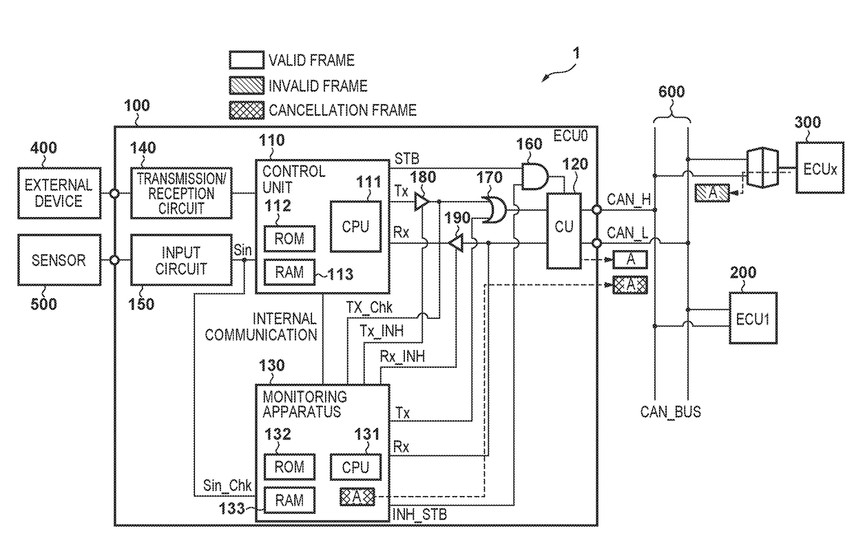
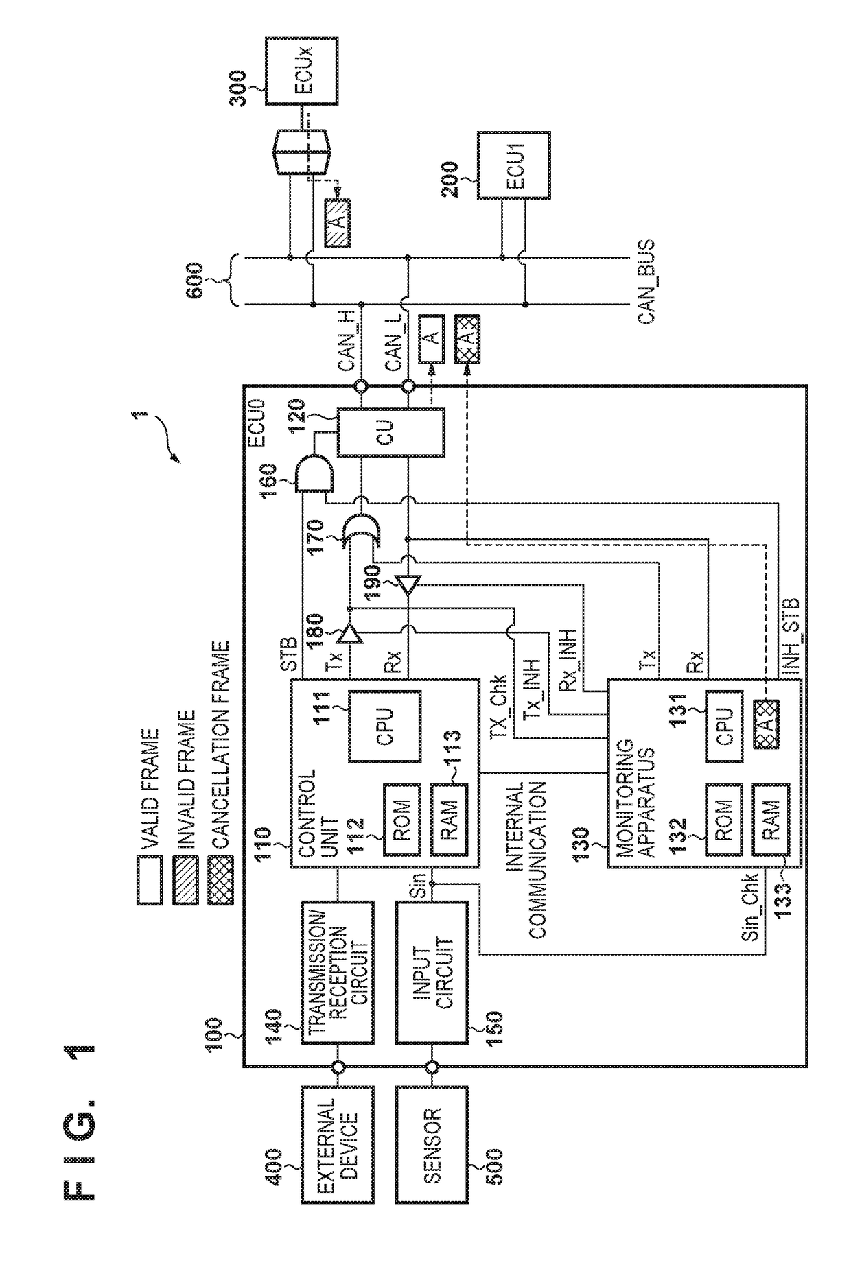
[0026]FIG. 1 is a block diagram showing the arrangement of an in-vehicle network according to an exemplary embodiment of the present invention.

[0027]As shown in FIG. 1, an in-vehicle network (to be referred to as a network hereinafter) 1 implements data communication when a plurality of ECUs (Electronic Control Units: control apparatuses) 100, 200, and 300 connected to a CAN bus 600 transmit / receive frames complying with the standard of the CAN bus. Note that for the sake of descriptive simplicity, the three ECUs are connected in this example. However, more ECUs are connected to an actual vehicle.

[0028]In the network 1, a monitoring apparatus 130 is incorporated in the ECU 100 (ECU0) for data security, and monitors the network 1. An external device 400 and a sensor 500 are connected to the ECU 100, and the operation of the external device 400 is electroni...


PUM


Abstract

A monitoring apparatus capable of efficiently disabling, when an invalid frame is detected in an in-vehicle network, the invalid frame by a simple method, for example, includes a reception unit configured to receive a frame from a communication network, a determination unit configured to determine whether the frame received by the reception unit is a valid frame or an invalid frame which is not a valid frame, and a transmission unit configured to transmit, if the determination unit determines that the received frame is an invalid frame, a frame including information identical to that included in the valid frame.

Description

CROSS-REFERENCE TO RELATED APPLICATION[0001]This application is based upon and claims the benefit of priority from the prior Japanese Patent Application No. 2016-051517, filed on Mar. 15, 2016, the entire contents of which are incorporated herein by reference.BACKGROUND OF THE INVENTION[0002]Field of the Invention[0003]The present invention relates to a monitoring apparatus and, more specifically, to a network monitoring apparatus for monitoring the operation status of a network mounted on a vehicle.[0004]Description of the Related Art[0005]Electronic control has been introduced in recent vehicles. ECUs for controlling the respective units of a vehicle are connected to, for example, a common bus according to an interface complying with the standard of a controller area network (CAN), and communicate with each other. Originally, an in-vehicle network is a network closed in a vehicle, and is isolated from the outside. However, it is necessary to communicate with the outside to update ...

Claims


Application Information

Patent Timeline
IPC IPC(8): H04L29/06G06F11/30
CPCH04L63/1416G06F11/3013H04L2012/40215G06F11/3006G06F11/3051H04L63/30H04L67/12H04L1/242H04L12/40013
Inventor WAKITA, KAZUYOSHI
Owner HONDA MOTOR CO LTD
Learn More