Low flow emitter with exit port closure mechanism for subsurface irrigation

a technology of exit port and subsurface irrigation, which is applied in the direction of couplings, instruments, process and machine control, etc., can solve the problems of insufficient rainfall in many parts of the world

Active Publication Date: 2017-11-14
HUNTER INDUSTRIES
View PDF76 Cites 17 Cited by
  • Summary
  • Abstract
  • Description
  • Claims
  • Application Information

AI Technical Summary

Problems solved by technology

Many areas of the world have insufficient rainfall during periods of the year to support the health of turf and landscaping.

Method used


Image

  • Low flow emitter with exit port closure mechanism for subsurface irrigation
  • Low flow emitter with exit port closure mechanism for subsurface irrigation
  • Low flow emitter with exit port closure mechanism for subsurface irrigation

Examples


first embodiment

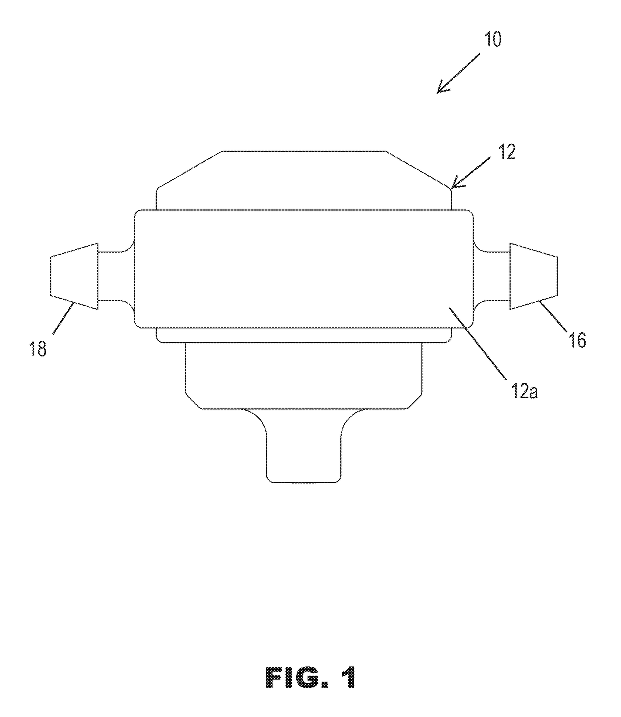
[0026]FIG. 1 illustrates a button style drip emitter 10 in accordance with the present invention. The drip emitter 10 is designed to be placed above ground, or buried in the ground near individual plants, shrubs and trees for accomplishing subsurface irrigation. Besides its stainless steel coil spring and synthetic rubber diaphragm and washer, the other parts of the drip emitter 10 are preferably made of injection molded thermoplastic such as polyethylene, polypropylene and blends thereof. The various parts of the drip emitter 10 may also be made of injection molded styrene or acrylonitrile butadiene styrene (ABS). Other plastic materials commonly used to mold irrigation parts may also be used and need not be listed herein.

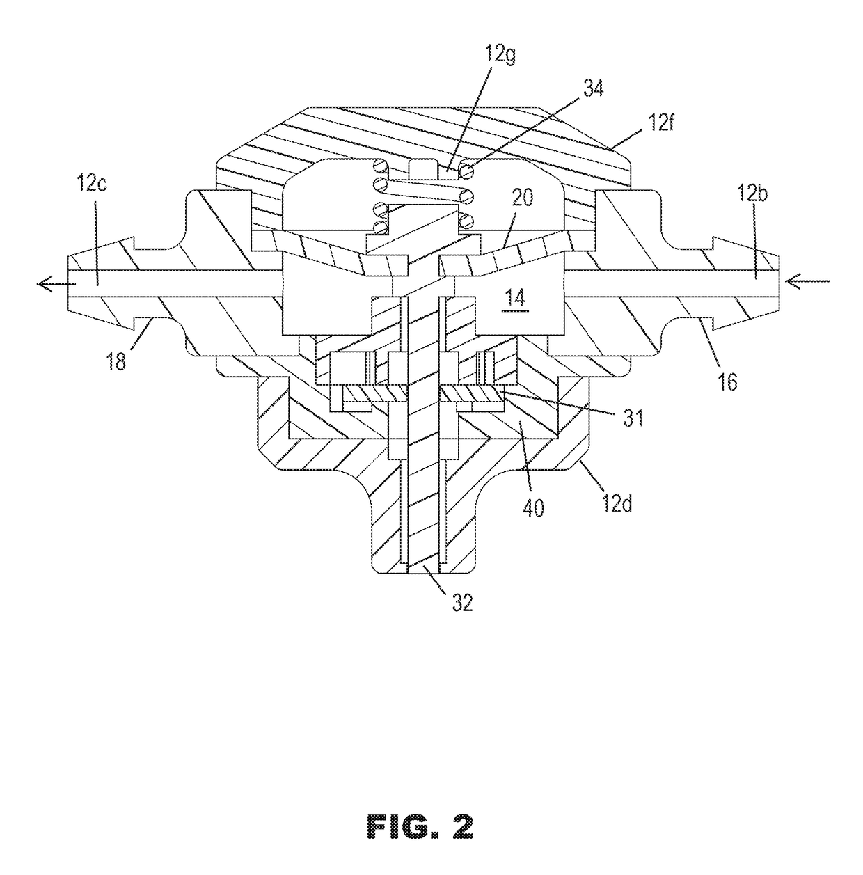
[0027]The drip emitter 10 includes a generally cylindrical valve chamber 12 defining a hollow interior 14 (FIG. 2). The annular side wall 12a (FIG. 1) of the valve chamber 12 has diametrically positioned entry and exit ports 12b and 12c (FIG. 2), respectively, for...

second embodiment

[0034]FIG. 7 illustrates a spike style drip emitter 40 in accordance with the present invention. The drip emitter 40 has a valve portion 42 similar to the button style drip emitter 10 except that the lower nipple portion 12d is replaced with an elongated lower ground spike portion 44. The drip emitter 40 is configured so that the lower pointed end 46 of the ground spike portion 44 can be manually pushed into the soil to anchor the emitter 40 with the valve portion 42 located above ground. The spike portion 44 is formed with four elongated vertical ribs 48 that are spaced ninety degrees apart. The lower pointed end 46 is similarly formed with four elongated vertical ribs 49 (FIG. 11). This cross configuration of the spike portion 44 provides sufficient rigidity and reduced cross-sectional area to ease the insertion of the spike portion 44 into the soil.

[0035]A greatly elongated pin 50 (FIG. 8) performs a similar function in the drip emitter 40 as the pin 32 performs in the drip emitt...

third embodiment

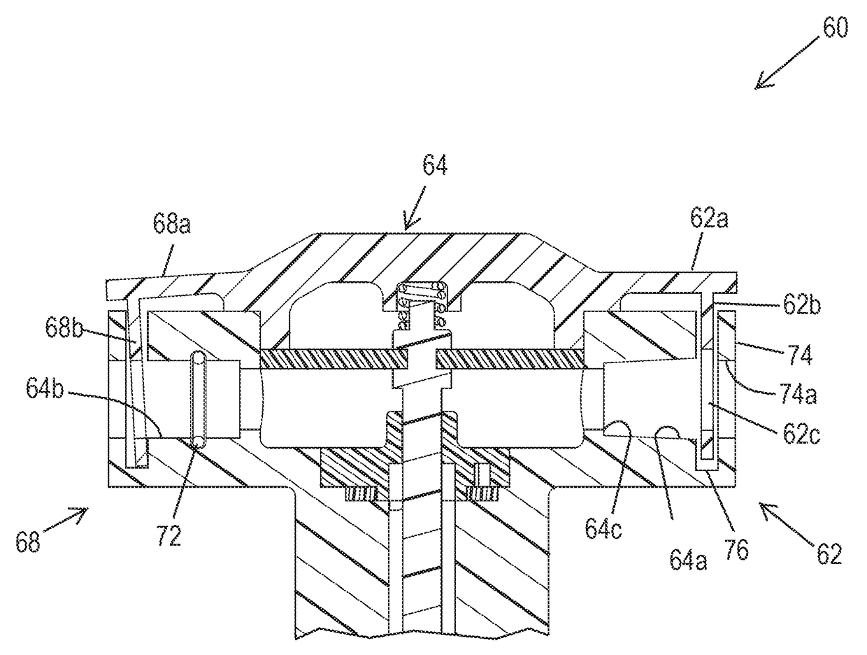
[0037]FIG. 13A illustrates the present invention in the form of a spike style drip emitter 60 with quick connect mechanisms for coupling drip line tubing to the drip emitter 60. The drip emitter 60 is generally similar in construction to the drip emitter 40 except for the utilization of the quick connect mechanisms in place of the barbed fittings 16 and 18. A first clamp fitting 62 is provided on an inlet side of a valve chamber 64 for coupling a first tube segment 66 (FIG. 15) to admit water from the first tube segment 66 through an entry port 64a (FIG. 13A). A second clamp 68 fitting (FIG. 13A) is provided on an outlet side of the valve chamber 64 for coupling a second tube segment 70 (FIG. 15) to deliver water from the hollow interior of the valve chamber 64 through an exit port 64b (FIGS. 13A and 13B) and into the second tube segment 70.

[0038]FIG. 14 illustrates two different tube segment coupling configurations on opposite sides of the drip emitter 60 for the sake of expediency...


PUM


Abstract

A drip emitter for subsurface irrigation includes a valve chamber defining a hollow interior, an entry port and at least one exit port. A flexible diaphragm is mounted in the hollow interior of the valve chamber for movement in response to pressurized water being supplied to the hollow interior through the entry port. The drip emitter further includes a tortuous path water flow channel that limits the flow of water from the hollow interior of the valve chamber to the at least one exit port. A closure member is moved by the flexible diaphragm to open the at least one exit port when pressurized water enters the hollow interior to allow water to be discharged through the at least one exit port. A spring moves the closure member to close the at least one exit port when the supply of pressurized water is shut OFF.

Description

CROSS-REFERENCE TO RELATED APPLICATION[0001]This application is a continuation of U.S. patent application Ser. No. 13 / 644,741, filed Oct. 4, 2012 and entitled “Low Flow Emitter with Exit Port Closure Mechanism for Subsurface Irrigation,” which is related by subject matter to U.S. patent application Ser. No. 12 / 693,342 (now U.S. Pat. No. 8,371,325, issued Feb. 12, 2013) filed by Glendale Grizzle on Jan. 25, 2010, entitled “Soil Moisture Responsive Irrigation Flow Control Valve,” which was assigned to Hunter Industries, Inc. on Apr. 30, 2010, on Reel 024319, Frame 0565. The entire disclosures of the above-referenced applications are hereby incorporated by reference.BACKGROUND OF THE INVENTION[0002]Field of the Invention[0003]The present invention relates to subsurface irrigation of landscape vegetation.[0004]Description of the Related Art[0005]Many areas of the world have insufficient rainfall during periods of the year to support the health of turf and landscaping. Irrigation systems...

Claims


Application Information

Patent Timeline
Patent Type & Authority Patents(United States)
IPC IPC(8): A01G25/02F16L37/084B05B1/30B05B1/32
CPCA01G25/023B05B1/323B05B1/3006F16L37/0841B05B12/088G05D7/0186
Inventor CLARK, MICHAEL L.HUNTER, DANIEL E.
Owner HUNTER INDUSTRIES
Why Eureka
Try Eureka