
Coupling device for a tube

a technology of coupling device and tube, which is applied in the direction of pipe-joints, fluid pressure sealed joints, sleeves/socket joints, etc., can solve the problems of completely losing the coupling with the tube, reducing the effectiveness of sealing action, and inability to guarantee the mutual positioning of these pressure element segments. , to achieve the effect of improving the effectiveness of the coupling devi

Active Publication Date: 2017-11-14
GEORG FISCHER WAGA
View PDF10 Cites 0 Cited by
  • Summary
  • Abstract
  • Description
  • Claims
  • Application Information

AI Technical Summary

Benefits of technology

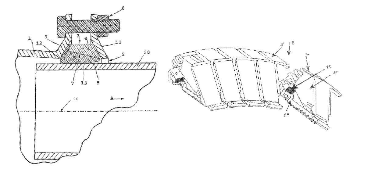
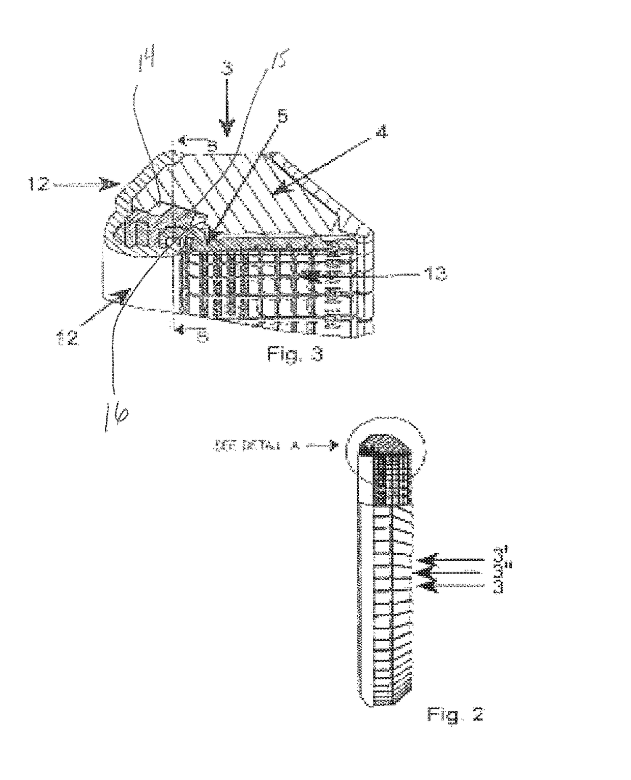
[0009]For a further improvement of the effectiveness of the coupling device according to the invention it is therefore proposed that of each pressure element the first pressure element segment is provided with a projection extending transversely to the longitudinal direction of the tube, and that said projection extends into a slit or slot that is provided in a directly neighboring second pressure element segment that forms part of a neighboring pressure element. This projection extending transversely to the longitudinal direction of the tube does not impact the assembly of the coupling device, which is done by making a complete ring of pressure elements that are of same shape and dimension, and this is irrespective whether or not the pressure elements are also embodied with the above-mentioned first projection at the extremity of the inclined contacting surfaces closest to the tube, which is provided on the first pressure element segment to limit the movement of the second pressure element segment.
[0011]Suitably a side wall of the slot provides a stop limiting the extension of the projection extending in said slot, so as to cause that longitudinal movement of the first pressure element segment and the second pressure element segment of any pressure element with respect to each other is limited. In this way the angle of inclination of the contacting surfaces of the first pressure element segment and the second element segment can be relatively small which is beneficial for effective sealing, without the danger that the functionality of the coupling device of the invention is lost when heavy tension strains are present between the tube and the coupling device.

Problems solved by technology

Due to the inclining contact surfaces of the separate pressure element segments, the absence of this projection could mean that the mutual positioning of these pressure element segments cannot be guaranteed.
A remaining problem with the known coupling device is the trade-off that exists between the angle of the inclination between the contacting surfaces of the first pressure element segment and the second pressure element segment on the one hand, and on the other hand the capability of the known coupling device to resist loss of operationability of the coupling device when heavy tension strains are applied to the tube, and at the same time to increase the effectiveness of the sealing action in that heavy tension strain situation.
Conversely the effectiveness of the sealing action decreases when the angle of inclination becomes too large.
A relatively small angle of inclination of said contacting surface enlarges however the danger that when heavy tension strains exist between the tube and the coupling device, the first pressure element segment initially enlarges the pressure exerted on the tube, yet with further increased tension strain will contract the tube and / or slip away from underneath the second pressure element segment, causing that the coupling with the tube is entirely lost.

Method used


Image

  • Coupling device for a tube
  • Coupling device for a tube
  • Coupling device for a tube

Examples


Embodiment Construction

[0023]Example embodiments will now be described more fully with reference to the accompanying drawings.

[0024]Whenever in the figures the same reference numerals are applied, these numerals refer to the same or similar parts.

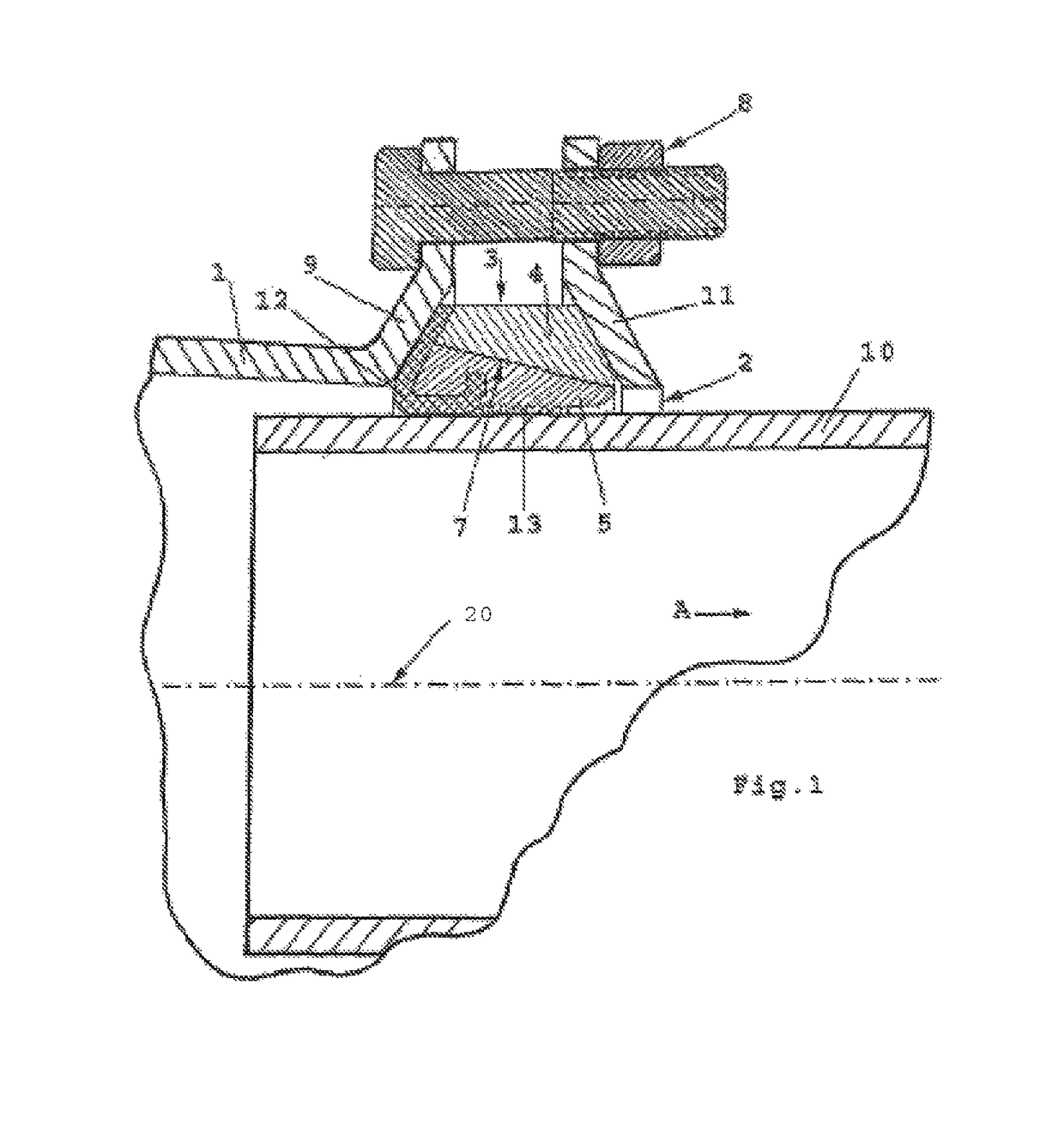
[0025]Referring first to FIG. 1 some aspects of the coupling device according to the invention will now be elucidated that the coupling device shares with the coupling device of the prior art.

[0026]The coupling device shown in FIG. 1 comprises a sleeve part 1 with an insert end 2 for the tube 10 having a longitudinal axis 20 and at least one pressure element 3 for exerting a clamping force on the tube 10. The pressure element 3 co-operates with a sealing organ 12, usually an element made of rubber, providing the actual seal around the tube 10.

[0027]At the side facing away from the tube, the at least one pressure element 3 is further provided with surfaces that converge in the radial direction, whose orientation corresponds to the orientation of the support walls ...


PUM


Abstract

The invention relates to a coupling device for coupling with a tube, comprising at least one pressure element for exerting a clamping force on the tube, wherein the said at least one pressure element is one of a series of correspondingly embodied neighboring pressure elements, wherein each pressure element of said series comprises a first pressure element segment and a second pressure element segment, and wherein the first pressure element segment is placed proximally and the second pressure element segment distally with respect to the tube, and that of each pressure element the first pressure element segment is provided with a protrusion extending transversely to the longitudinal direction of the tube, and that said protrusion extends into a slot that is provided in a directly neighboring second pressure element segment that forms part of a neighboring pressure element.

Description

CROSS-REFERENCE TO RELATED APPLICATIONS[0001]This application is a 371 National Stage of International Application No. PCT / EP2013 / 075597, filed on Dec. 5, 2013, and published in English as WO 2014 / 090667 A1 on Jun. 19, 2014. This application claims the benefit and priority of The Netherlands Application No. 2009953, filed on Dec. 10, 2012. The entire disclosures of the above applications are incorporated herein by reference.BACKGROUND[0002]This section provides background information related to the present disclosure which is not necessarily prior art.TECHNICAL FIELD[0003]The present invention relates to a coupling device for coupling with a tube, comprising at least one pressure element for exerting a clamping force on the tube, wherein the said at least one pressure element is one of a series of correspondingly embodied neighboring pressure elements, wherein each pressure element of said series comprises a first pressure element segment and a second pressure element segment, and w...

Claims


Application Information

Patent Timeline
Patent Type & Authority Patents(United States)
IPC IPC(8): F16L17/00F16L21/08F16L21/04
CPCF16L21/08F16L21/04
Inventor HULSEBOS, MICHEL PAULWIJLENS, JEROEN HERMANUS JOHANNESGIESEN, LEONARDUS HENRICUS WILHELMUS
Owner GEORG FISCHER WAGA
Learn More