Shrink tube insulation apparatus

a technology of shrink tubing and insulation apparatus, which is applied in the direction of insulation conductor/cable, cable/conductor manufacture, electric cable installation, etc., can solve the problems of high risk to both material and shrink tubing, and achieve the effects of preventing un-desired twisting, bending, and kinking of material

Active Publication Date: 2017-11-14
FLORIDA STATE UNIV RES FOUND INC
View PDF10 Cites 2 Cited by
  • Summary
  • Abstract
  • Description
  • Claims
  • Application Information

AI Technical Summary

Benefits of technology

[0013]The novel structure includes a device that can not only sheath short lengths of shrink tubing on to material but also sheath long lengths of material with shrink tubing as well. Varying embodiments of this device can insulate whole lengths of material with shrink tubing as well as covering certain sections of material for a more precise application.
[0014]This invention also provides the safety, consistency, and reproducibility of work desired when applying shrink tubing on wire, tape, or cable. Channels in the tracks constrict the movement of the material preventing un-desired twisting, bending, and kinking of the material. Whereas, for example, applying shrink tubing onto material by hand or on a machine that is not suited to handle fragile material puts high risk to both the material and shrink tubing. All embodiments of this device are suited for such fragile material and can sheath such material safely and efficiently.

Problems solved by technology

Whereas, for example, applying shrink tubing onto material by hand or on a machine that is not suited to handle fragile material puts high risk to both the material and shrink tubing.

Method used


Image

  • Shrink tube insulation apparatus
  • Shrink tube insulation apparatus
  • Shrink tube insulation apparatus

Examples


Embodiment Construction

[0023]In the following detailed description of the preferred embodiments, reference is made to the accompanying drawings, which form a part thereof, and within which are shown by way of illustration specific embodiments by which the invention may be practiced. It is to be understood that other embodiments may be utilized and structural changes may be made without departing from the scope of the invention.

Glossary of Claim Terms

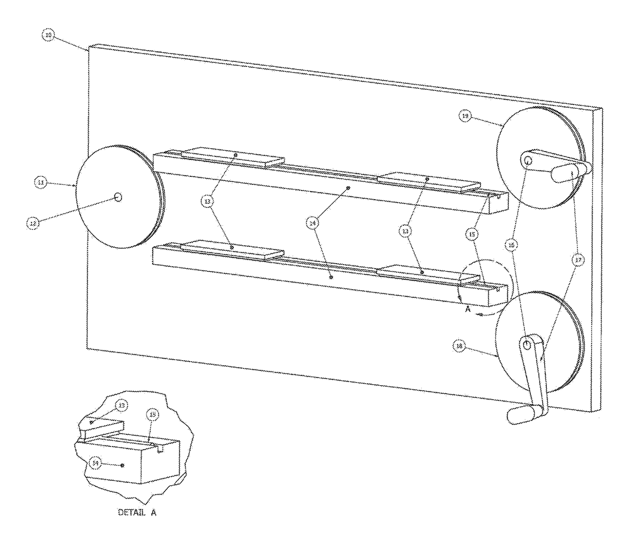
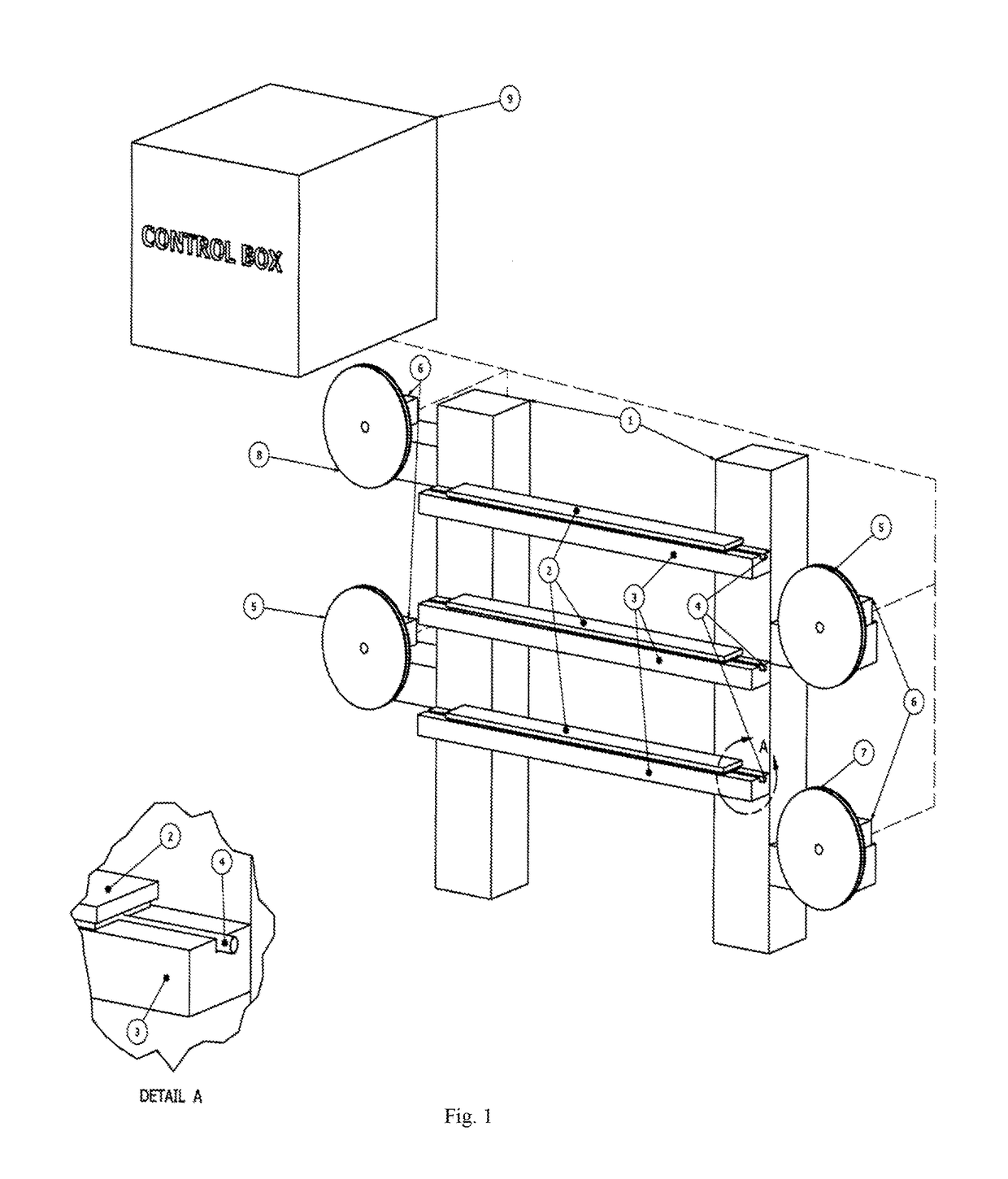
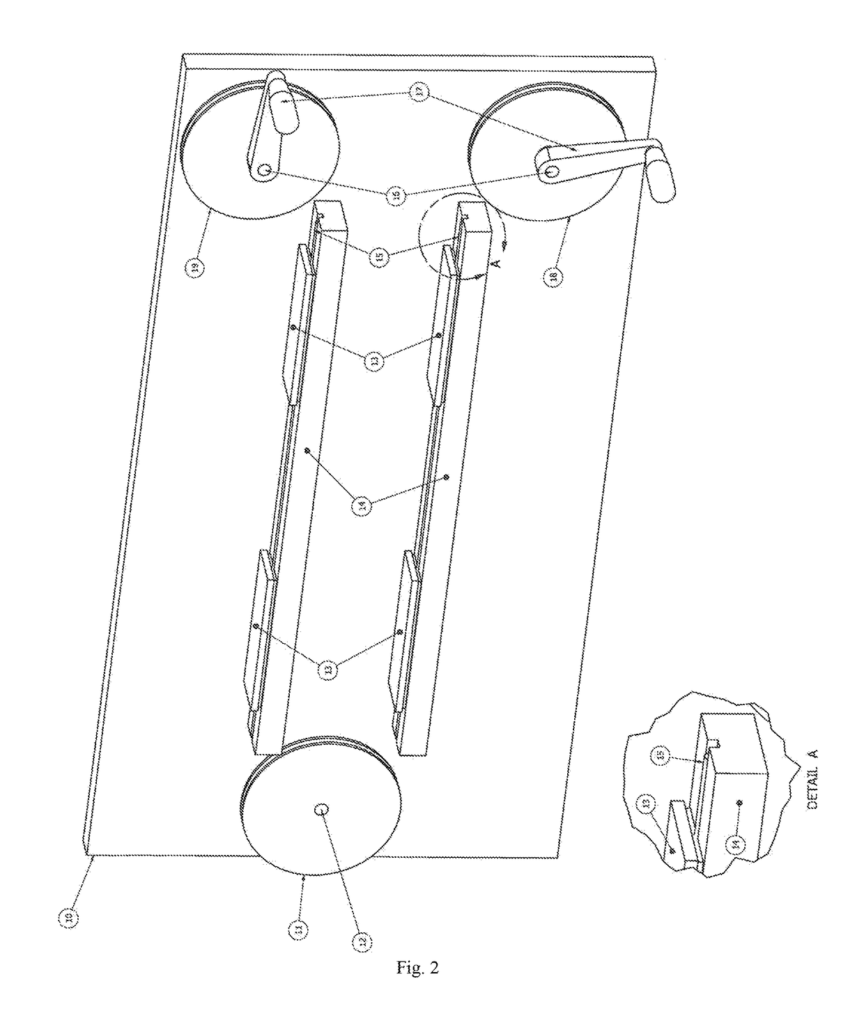
[0024]Spool: is a structure capable of rotating about an axis and adapted to hold some amount of material wrapped about the structure in an orientation perpendicular to the rotational axis.

[0025]Material: is a flexible member having a length greater than its width.

[0026]Tubular Insulation: is any hollow body.

[0027]String: is any flexible member having a cross-sectional area small enough to pass through the tubular insulation.

[0028]Cross-Sectional Area: is the area of a two-dimensional plane that extends outward in a radial or transverse direction and is create...


PUM

PropertyMeasurementUnit
insulatingaaaaaaaaaa
cross-sectional areaaaaaaaaaaa
areaaaaaaaaaaa

Abstract

A device and method for sheathing shrink tubing onto materials such as wire, tape, or cables. The device cannot only sheath short lengths of shrink tubing onto material, but also sheath long lengths shrink tubing onto material. Varying embodiments of this device can insulate whole lengths of material with shrink tubing as well as covering certain sections of material for a more precise application.

Description

CROSS-REFERENCE TO RELATED APPLICATIONS[0001]This nonprovisional application claims priority to provisional application No. 61 / 885,847, entitled “SHRINK TUBE INSULATION APPARATUS,” filed Oct. 2, 2013 by the same inventors.FEDERALLY SPONSORED RESEARCH OR DEVELOPMENT[0002]This invention was made with Government support under Grant Nos. DMR #0654118 and DMR #1157490 awarded by the National Science Foundation. The government has certain rights in the invention.BACKGROUND OF THE INVENTION[0003]1. Field of the Invention[0004]This invention relates, generally, to sheathing of shrink tubing. More specifically, it relates to an apparatus capable of applying shrink tubing onto long or short lengths of wires, tapes, and cables.[0005]2. Brief Description of the Prior Art[0006]Devices and methods for sheathing shrink tubing are well documented in the art. Most of these devices and methods apply shrink tubing to the ends of wire or cable bundles. The purpose for the application of the shrink tube...

Claims


Application Information

Patent Timeline
Patent Type & Authority Patents(United States)
IPC IPC(8): H01B13/06H02G1/08
CPCH01B13/062H02G1/083Y10T29/49117H01B13/01263
Inventor WHITTINGTON, ANDREW DAVIDDALBAN-CANASSY, MATTHIEUHILTON, DAVID K.TROCIEWITZ, ULF P.STARCH, WILLIAM L.SHEPPARD, WILLIAM R.MANKIN, ALEXANDERWHITTINGTON, JOE W.
Owner FLORIDA STATE UNIV RES FOUND INC
Why Eureka
Try Eureka