
Integrated customer contact center testing, monitoring and diagnostic systems

a customer contact center and monitoring system technology, applied in the field of contact center monitoring, communications systems and testing systems, can solve the problems of post negative reviews, all communication systems and/or networks are, unfortunately, susceptible to periodic malfunctions and failures, frustrated and dissatisfied,

Active Publication Date: 2017-11-14
INTEGRATED RES
View PDF11 Cites 2 Cited by
  • Summary
  • Abstract
  • Description
  • Claims
  • Application Information

AI Technical Summary

Benefits of technology

The patent describes a new invention and its preferred embodiments. The technical effects of the invention are not limited to the specific combinations described here and can be used in other combinations or isolated without changing the scope of the invention.

Problems solved by technology

All communication systems and / or networks are, unfortunately, susceptible to periodic malfunctions and failure.
When a system for communicating with customers malfunctions or fails, the customer may become frustrated and dissatisfied, which may also cause such customer to post negative reviews via various social media and review websites.
However, there is no ability to inject calls into the contact center system from the public telephone exchange or control the activity of the incoming calls.
Moreover, the internal monitoring and diagnostic software is not capable of testing the contact center's operations as a customer would experience them and determine whether any irregularities or other indicators of impending malfunction or failure are occurring.
But conventional external testing systems are unable to determine the root cause of the noted failure / irregularity / malfunction because there is no interface to diagnose the contact center's actual systems.
And without such diagnosis, automated correction of the failure cannot be performed.
Additionally, public telephone infrastructure and hardware limitations can cap the number of simultaneous calls that a given testing services vendor can employ from a given location.
Maintaining multiple locations is, of course, very expensive.

Method used


Image

  • Integrated customer contact center testing, monitoring and diagnostic systems
  • Integrated customer contact center testing, monitoring and diagnostic systems
  • Integrated customer contact center testing, monitoring and diagnostic systems

Examples


Embodiment Construction

[0026]In the following descriptions, the present invention will be explained with reference to various exemplary embodiments. Nevertheless, these embodiments are not intended to limit the present invention to any specific example, environment, application, or particular implementation described herein. Therefore, descriptions of these example embodiments are only provided for purpose of illustration rather than to limit the present invention.

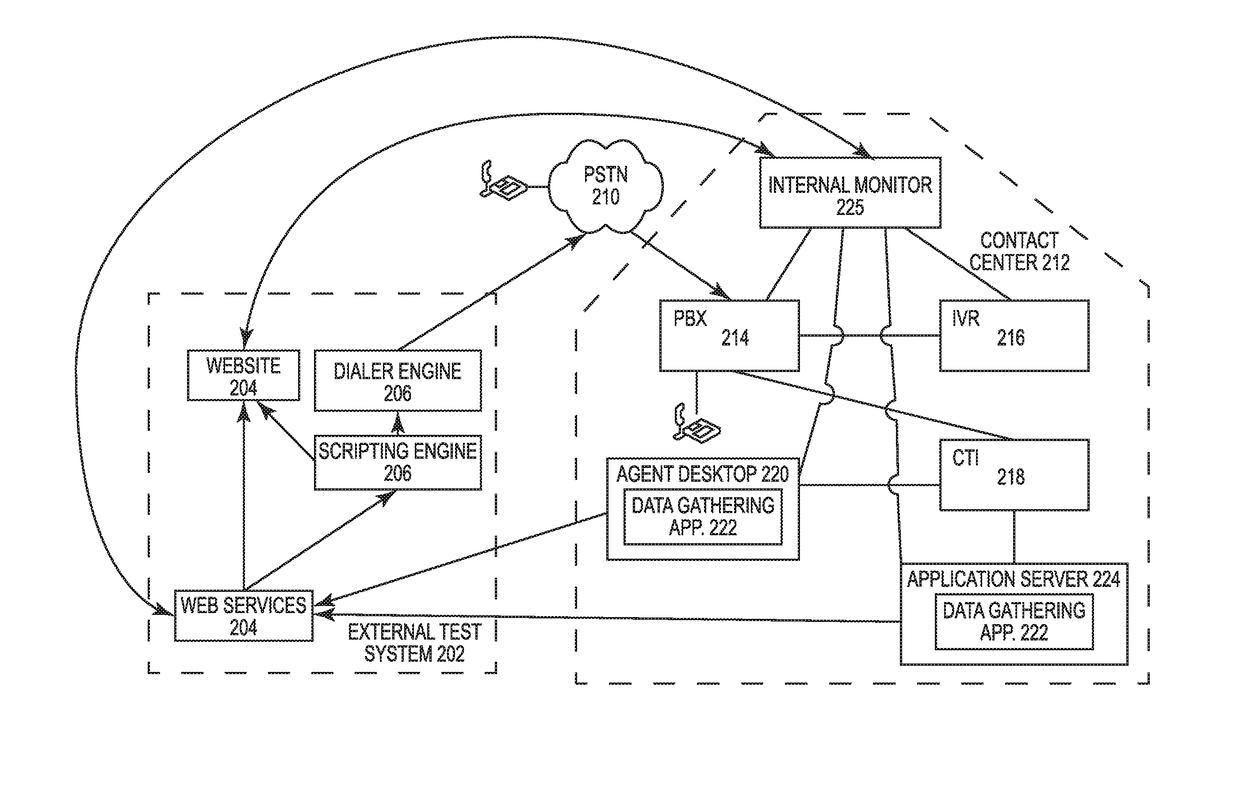
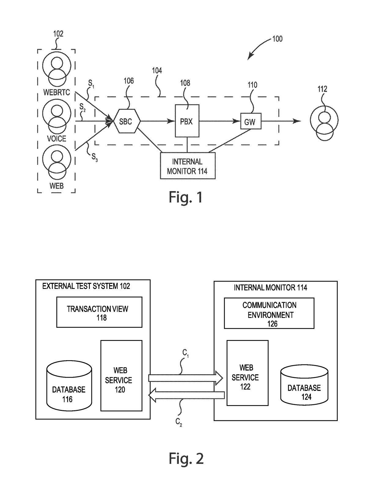
[0027]Referring to FIG. 1, a diagram of an integrated contact center testing, monitoring and diagnostic system 100 is provided. The system generally includes an external testing system 102 that can launch one or more test stimuli S1, S2 S3, etc. into a customer contact center 104. The contact center receives the incoming stimuli and routes it through a plurality of subsystems, such as a session border controller (SBC) 106, a PBX system 108, a gateway (GW) 110 and an IVR system (not shown in FIG. 1), before ultimately being routed, if applicable,...


PUM


Abstract

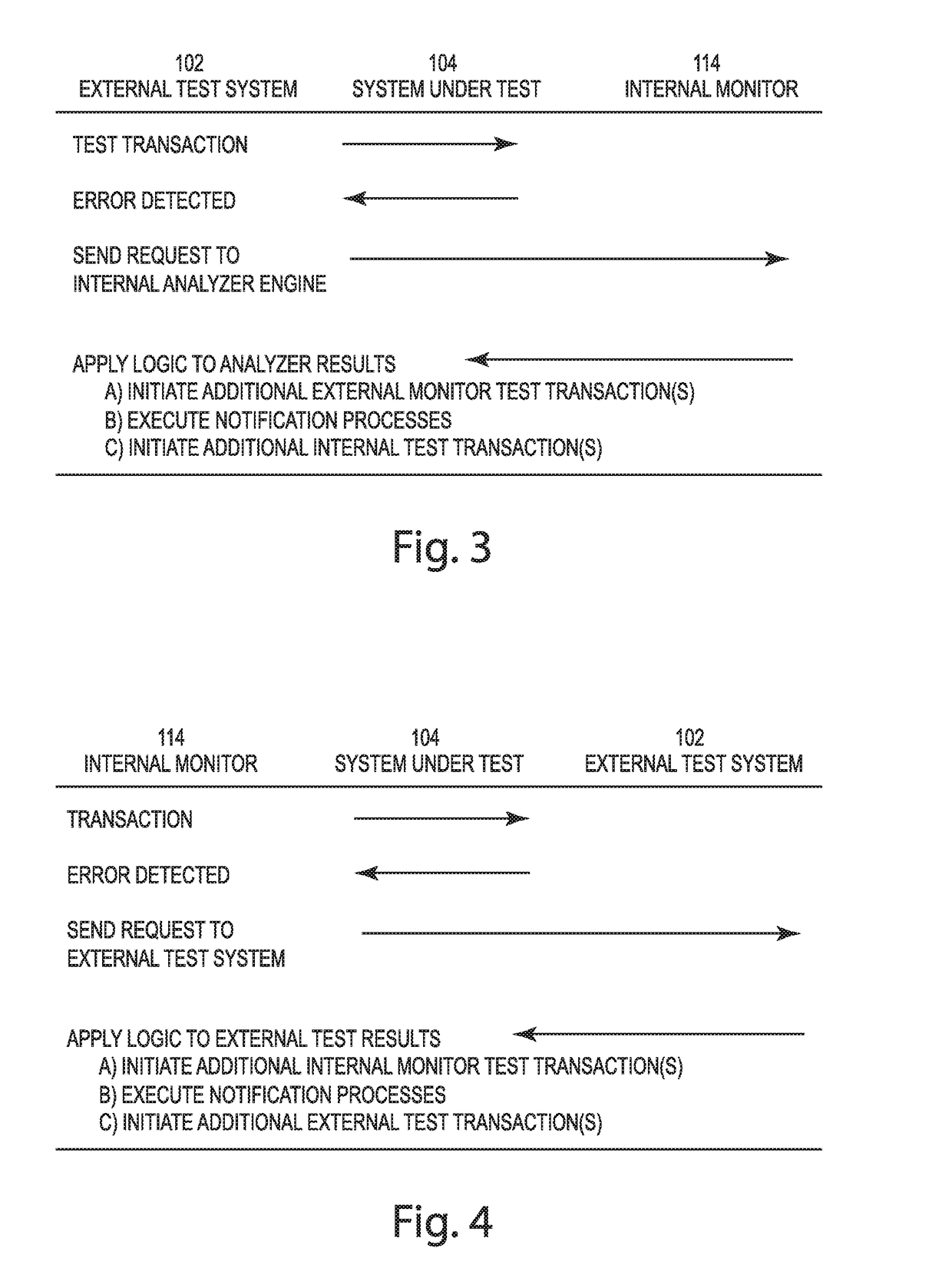
An external contact center testing system is integrated with an internal monitoring and diagnostic system to identify and verify a fault condition, and to determine the cause of such fault condition. Test data for each of the stimuli launched into the call center from the external testing system are synced with the monitoring results data generated by the internal monitoring system. The synced results can be analyzed to verify that a true fault has occurred and also to identify both failure conditions and specific hardware malfunctions giving rise to the noted failure. The internal monitoring system can interface with the external testing system to cause one or more testing stimuli to be launched by external testing system. The internal monitoring data can also be linked to the external testing data for drill-down viewing by a user.

Description

PRIORITY[0001]This application claims the priority benefit of U.S. Provisional Application No. 62 / 106,952, filed on Jan. 23, 2015, which is hereby incorporated herein by reference in its entirety.FIELD[0002]The present invention relates generally to contact center monitoring, communications systems and testing systems, and more particularly, to integrated internal and external testing and monitoring systems for contact centers.BACKGROUND[0003]A linchpin of success for any business is its ability to communicate effectively with its customers. One of the primary means of communication a business has with its customers is through a contact center. In a contact center, typically a customer telephone call is launched through the telephone network and is received by the call center portion of the business' contact center. Then a series of prompts query the customer for their account data and purpose of the call. The customer inquiry is next routed to an appropriate agent (either virtual o...

Claims


Application Information

Patent Timeline
Patent Type & Authority Patents(United States)
IPC IPC(8): H04M1/24H04M3/08H04M3/22H04M3/24H04M3/51
CPCH04M3/242H04M3/5166
Inventor ZILLES, RUSSELLBRICKEY, SHANBURKE, MICHAELCAFFARI, ALESSANDRODORRINGTON, CHRISTOPHERBABURIN, ALEXANDER
Owner INTEGRATED RES
Learn More