
Concealed sprinkler head cover adjusting device

a technology of adjusting device and concealed sprinkler, which is applied in fire rescue and other directions, can solve the problems of inadequate mounting stability and robustness of the head cover with the opposing bars of the frame, easy shaking increased clamping position of the head cover, so as to increase the range of clamping position, increase the space in the shell, and increase the movement range of the shell when covering the valve body

Active Publication Date: 2017-11-21
PROTECTOR SAFETY IND LTD
View PDF8 Cites 1 Cited by
  • Summary
  • Abstract
  • Description
  • Claims
  • Application Information

AI Technical Summary

Benefits of technology

The present invention is a sprinkler head that has a wider range of positions it can hold a valve body, and it has a space to hold the valve body in the shell. This makes the sprinkler head easier to install and makes it more aesthetically pleasing because it is closer to the ceiling. Overall, the invention improves the functionality and appearance of the sprinkler head.

Problems solved by technology

However, the contact area between the head cover and the opposing bars of the frame is limited, and thus the head cover is easy to be shaken when it is subject to an external vibration.
Thus, the mounting stability and robustness of the head cover with the opposing bars of the frame is inadequate.
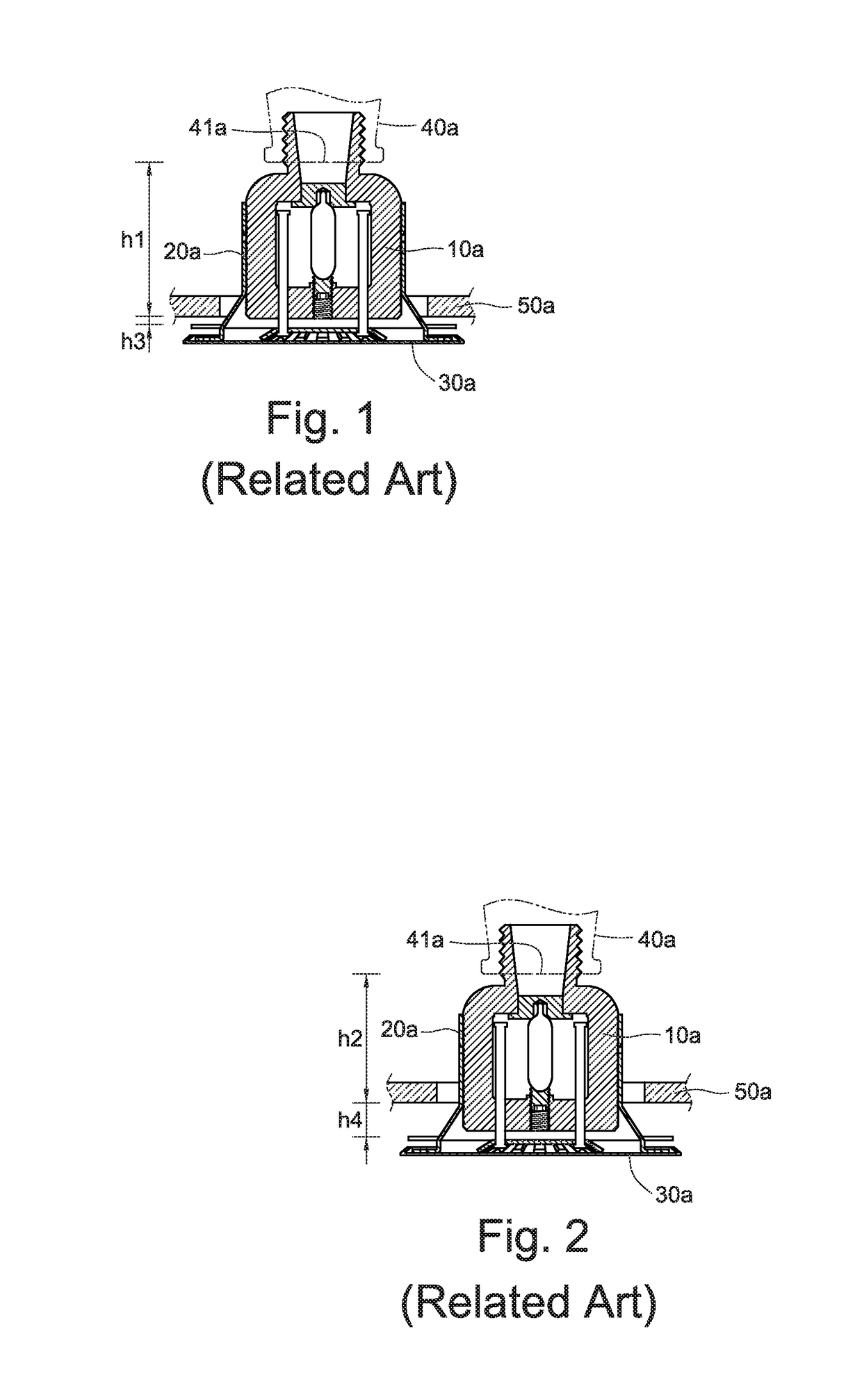
Although the aforementioned patent can solve the stability problem, however, since the concealed type sprinkler head is disposed at the water outlet of the fire water supply, and the fire water supply is arranged according to the structure of the building, the distance between the water outlet of the fire water supply and the ceiling is different, which may results in significant and noticeable height differences between the head cover disposed on the concealed sprinkler head and the ceiling.

Method used


Image

  • Concealed sprinkler head cover adjusting device
  • Concealed sprinkler head cover adjusting device
  • Concealed sprinkler head cover adjusting device

Examples


Embodiment Construction

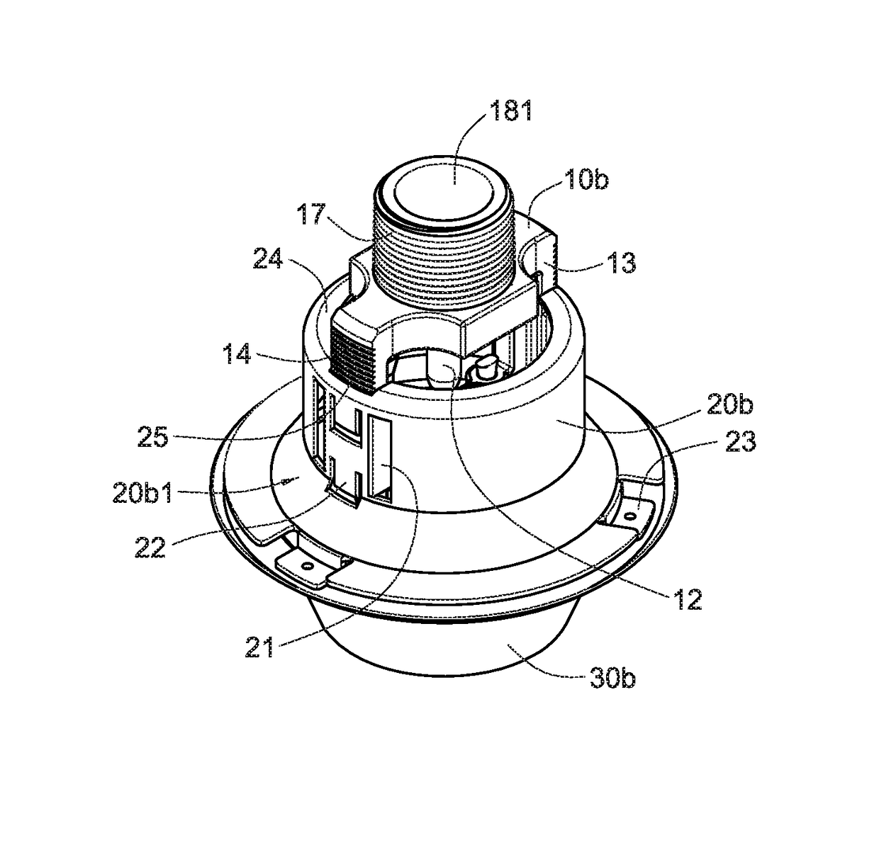
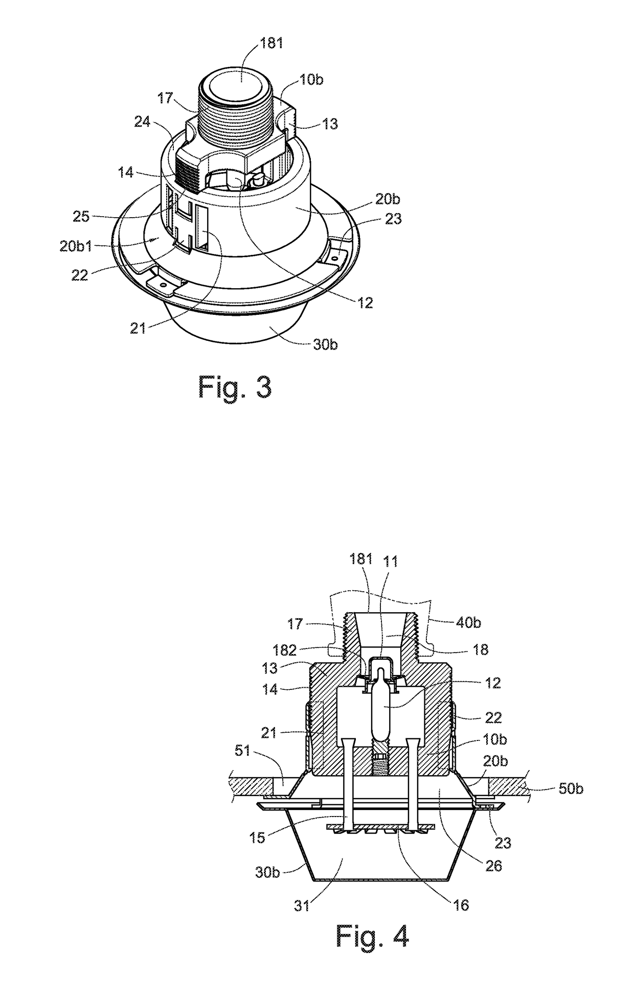
[0020]Refer to FIGS. 3 and 4, the concealed sprinkler head cover adjusting device includes a valve body 10b, a shell 20b, and bottom cover 30b.

[0021]The valve body 10b in formed with a screwing part 17 on the top thereof. The valve body 10b can be connected to a fire water supply 40b via the screwing part 17, and is exposed to the living area via a through hole 51 of the ceiling 50b. A flow channel 18 is formed inside the valve body 10b, and both ends of the flow channel 18 are respectively formed a water inlet 181 and a valve opening 182 at the surface of the valve body 10b. The flow channel 18 communicates with the fire water supply 40b via the water inlet 181 to allow the water in the fire water supply 40b flowing into the flow channel 18 from the water inlet 181 and flowing out of the flow channel 18 through the valve opening 182. The valve opening 182 is blocked by a water valve 11. The water valve 11 can control the timing of supplying water from the fire water supply 40b. A ...


PUM


Abstract

A concealed sprinkler head cover adjusting device includes a valve body formed with a flow channel therein. Both sides of the valve body are formed with an opposing bar along the axial direction of the flow channel. A shell is clamped on the opposing bars and is formed with a first accommodating space. A bottom cover is fixed to the bottom of the shell and is inwardly concaved formed a second accommodating space. A restriction site is formed on the outer wall of the opposing bars along the axial direction of the flow channel, both sides of the shell are symmetrically formed with a guiding part and a plurality of clamping parts, and the guiding parts guide the opposing bars to allow the clamping parts adjust the clamping position on the restriction site, thereby adjusting the position of the valve body in the first and second accommodating spaces.

Description

TECHNICAL FIELD[0001]The technical field relates to a structure of a concealed sprinkler head cover, particularly to a concealed sprinkler head cover adjusting device.RELATED ART[0002]The conventional fire sprinkler head can be classified as concealed type, semi-concealed type, and open type. The concealed type is to hide the sprinkler head and the connected fire water supply into the ceiling, and only a head cover is exposed outside the ceiling.[0003]The head cover of the traditional concealed type sprinkler head is formed with internal threads, and the outer wall of the opposing bars on both sides of the valve body of the sprinkler head is formed with external threads. Through the engagement between the internal threads of the head cover and the external threads of the opposing bars, the head cover can be mounted to the valve body. However, the contact area between the head cover and the opposing bars of the frame is limited, and thus the head cover is easy to be shaken when it is...

Claims


Application Information

Patent Timeline
Patent Type & Authority Patents(United States)
IPC IPC(8): A62C37/12A62C35/68A62C37/09A62C37/14
CPCA62C37/09A62C37/14A62C35/68
Inventor CHEN, JUNG-WEN
Owner PROTECTOR SAFETY IND LTD
Learn More