Barrier wall system and method

a barrier wall and wall technology, applied in the direction of walls, traffic restrictions, roads, etc., to achieve the effect of shortening the time period and lowering the cos

Inactive Publication Date: 2017-11-21
HARKINS JOHN
View PDF15 Cites 7 Cited by
  • Summary
  • Abstract
  • Description
  • Claims
  • Application Information

AI Technical Summary

Benefits of technology

[0004]The barrier modules can be prefabricated in factories and shipped in one piece for field erection for expedient, rapid, and safer installation, made possible by the unique and adjustable end connectors which insures that each prefabricated module may be connected with each other as a true match at any variation in elevation in ground topography.
[0008]Solar film elements can be applied to either or both sides of the module and collection wiring and terminal conversion to solar energy to transfer to local utilities is possible, which is an advantage of the modules and barrier wall of the invention since the modules include large flat areas suitable for solar energy systems. In some embodiments the slotted connectors include two holes for receiving bolts, one of which is distal and the other proximal, wherein the distal holes are aligned with an area within the frame and the proximal holes are forward of the front plate. The slotted connectors are arranged on the front side plate and vary in width, with the widest slotted connector nearest to the bottom of the module and above the concrete foundation, and the narrowest slotted connector nearest the top of the module. The slotted connectors have an open side and a closed side, with the open side being open toward the front of the module and the closed side fastened to the member of the frame supporting the rear side. The slotted connectors are designed to receive matching extenders within the slots. The extenders are used to compensate for differences in width when two modules at different elevations are to be joined together, in which case a proximal hole of a wider slotted connector is bolted to an extender in a slot of a less wide slotted connector, thereby allowing easy and efficient connection between modules at different elevations from each other.

Problems solved by technology

Prior barrier systems consisted of fences, concrete walls, and the like, which suffered from deficiencies such as penetrability, cost, and long construction periods required.

Method used


Image

  • Barrier wall system and method
  • Barrier wall system and method
  • Barrier wall system and method

Examples


Embodiment Construction

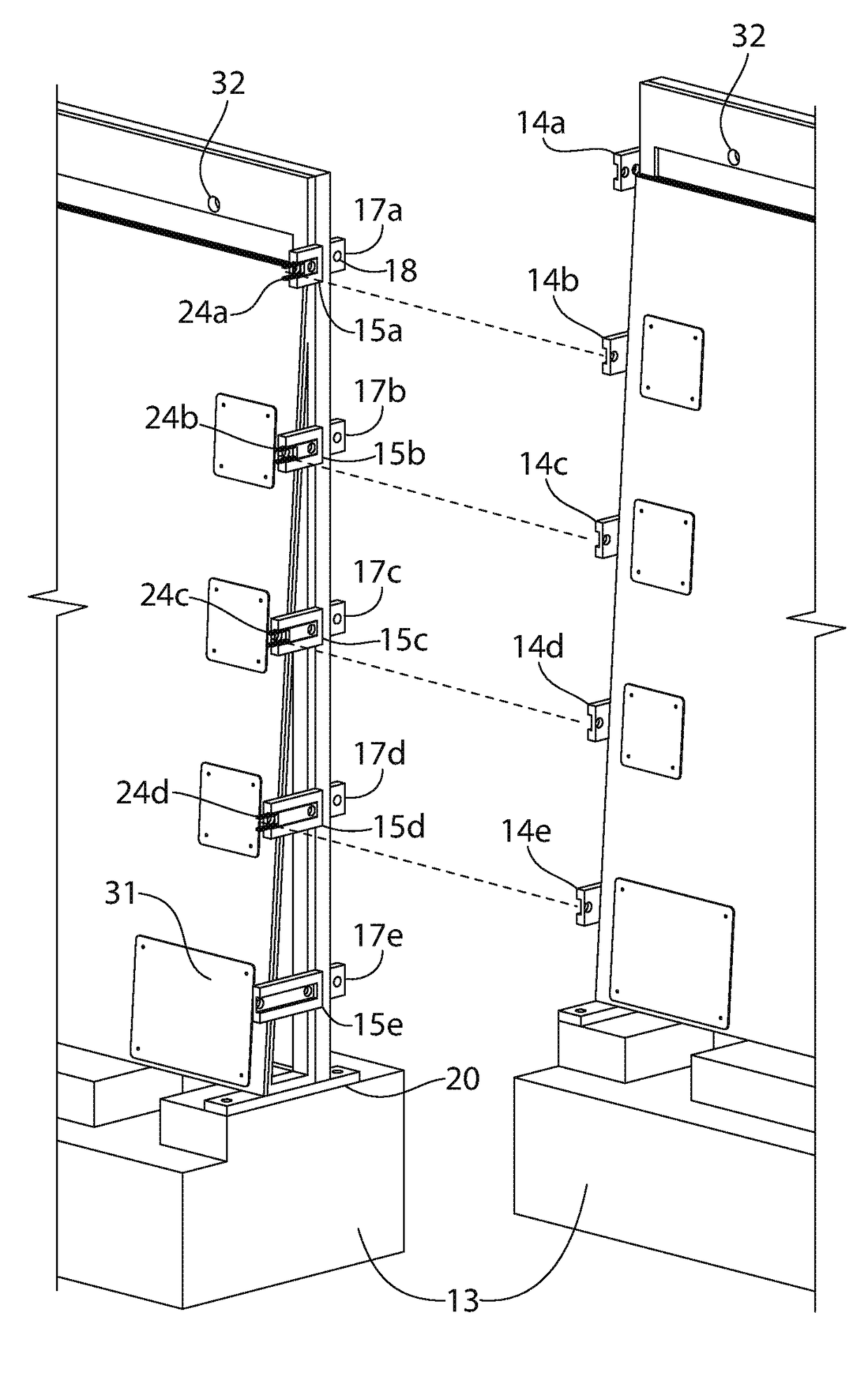
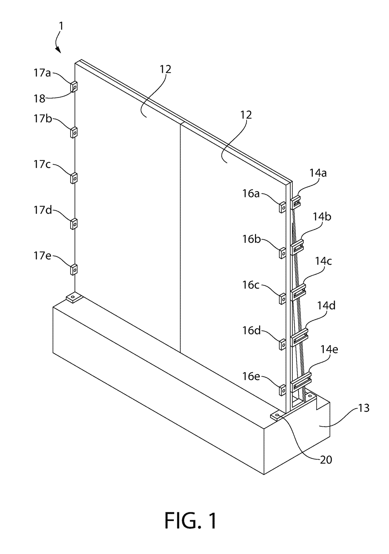
[0034]Referring now to the drawings, FIG. 1 illustrates an embodiment of a barrier module 1 of the invention which includes rear side plates 12 which face the direction of the potential intruders. The rear side plates 12 and front side plates 11 (FIG. 2) are supported in a frame 21 (FIG. 3) which is attached via bolts 20 to a concrete foundation 13 which can be included in the prefabricated module. Left end rear side connectors 16a-16e and right end rear side are attached to rear side plates 12. Left end front side slotted connectors 14a-14e are attached to the front side plate 11 (FIG. 2) and the frame 21 (FIG. 3) so that one hole is adjacent to the triangular open area of the frame.

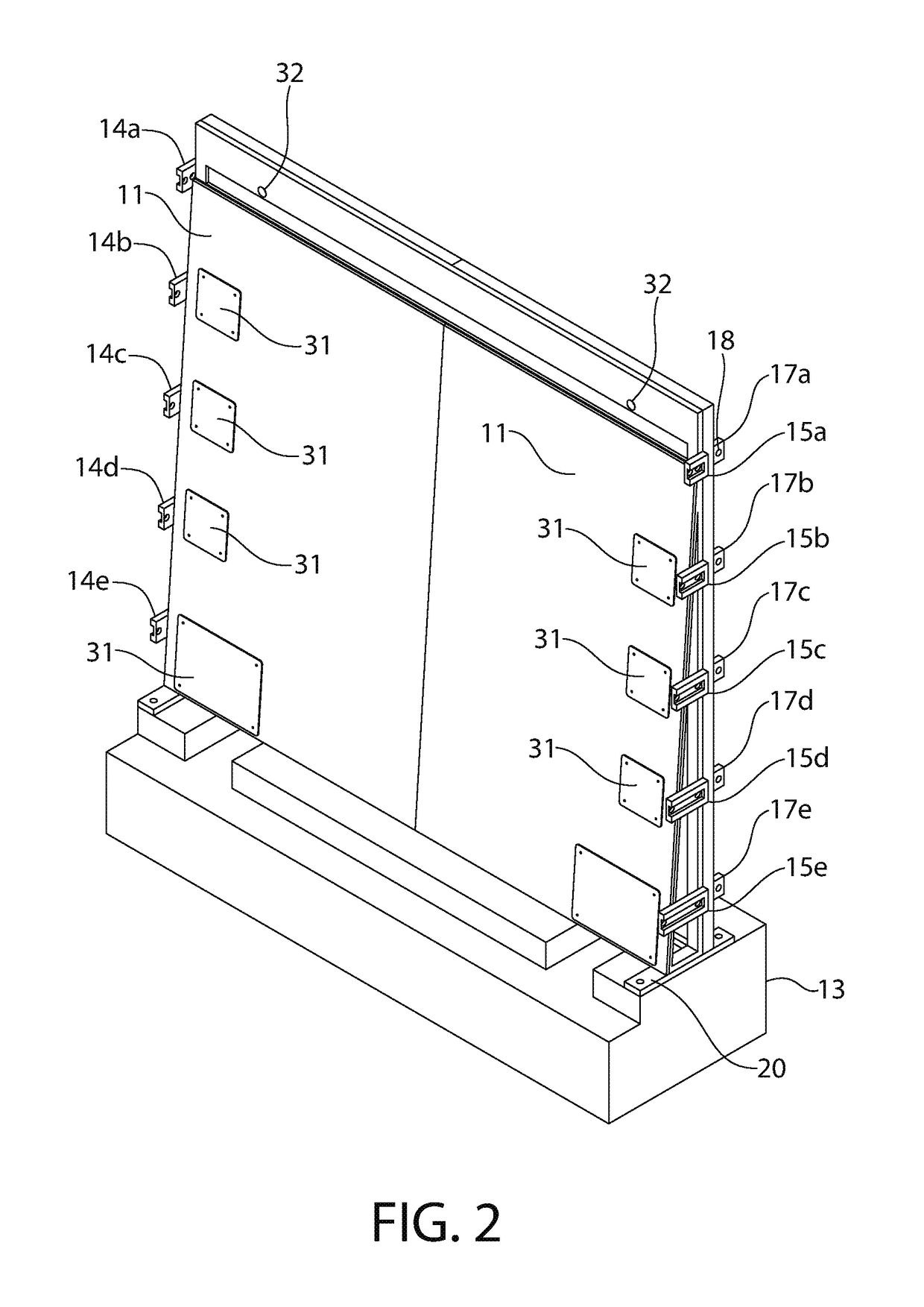
[0035]FIG. 2 illustrates the front side of the module 1 wherein front side plates 11 are supported on the frame at an angle off of vertical. Left end front side slotted connectors 14a-14e are shown in this view, as are right end front side slotted open-ended connectors 15a-15e and right end rear side co...


PUM


Abstract

A barrier system constructed of modules which includes a frame, a concrete foundation, a frame attached to the concrete foundation and supporting a non-vertical front side plate and a vertical rear side plate so that the front side plate and rear side plate meet at the top and are spread apart from each other at the bottom, slotted connectors on the front side and connectors on the rear side, the module adapted to be joined to an adjacent module either at the same elevation or a different elevation. The modules are joined together via bolts in the rear side connectors and threaded toggle bolts and drop toggle nuts through the front side slotted connectors. Extenders within the slots of the open ended connectors are used when connecting adjacent modules at different elevations to accommodate for slotted connectors of different sizes which must be connected to each other.

Description

BACKGROUND OF THE INVENTION[0001]This invention relates to the field of barrier systems designed to prevent entry by unauthorized persons and vehicles into protected property.[0002]Prior barrier systems consisted of fences, concrete walls, and the like, which suffered from deficiencies such as penetrability, cost, and long construction periods required.SUMMARY OF THE INVENTION[0003]The present invention can be constructed and installed at lower cost and within shorter time periods than prior barrier systems and comprises in one aspect a barrier system comprising at least one module which includes a frame, a concrete foundation, a frame attached to the concrete foundation and supporting a non-vertical front side plate and a vertical rear side plate on a frame so that the front side plate and rear side plate meet at the top of the frame and are spread apart from each other at the bottom, slotted connectors on the front side and connectors on the rear side, the module adapted to be joi...

Claims


Application Information

Patent Timeline
Patent Type & Authority Patents(United States)
IPC IPC(8): E01F13/00E04H17/14E04H17/16E01F15/08E04B2/74E04B2/72
CPCE04H17/166E04B2/72E04B2/7416E01F15/088E01F13/00E04H17/16E01F13/02
Inventor HARKINS, JOHN
Owner HARKINS JOHN
Why Eureka
Try Eureka