Augmentation of a dynamic terrain surface

a dynamic terrain and surface technology, applied in the field of augmented reality, can solve the problems of prolonging the disruption caused, high-risk excavation, and potentially serious injuries and damag

Active Publication Date: 2017-11-21
BENTLEY SYST INC
View PDF8 Cites 56 Cited by
  • Summary
  • Abstract
  • Description
  • Claims
  • Application Information

AI Technical Summary

Problems solved by technology

Excavation is typically a high-risk operation.
During excavation, subsurface features (i.e., water pipes, gas pipes, sewer pipes, electrical lines or other below-grade utilities or obstructions) may be struck by excavators causing potentially serious injuries and damage.
Any repairs necessitated by the damage may lengthen the disruption caused the by the excavation.
For example, if the excavation is part of a road work project and a water pipe is struck and damaged, the time needed to repair the damage may significantly lengthen any traffic disruption already caused by the project, and impose a further burden on local residents and businesses.
One of the main causes of subsurface utilities strikes is uncertainty on behalf of the excavator operator as to the location of the utilities.
First, colored spray paint markings are short lived.
Since the markings are painted on the ground directly where the excavation is to occur, as soon as the excavation begins the markings are generally destroyed and the information is lost.
Second, colored spray paint markings do not provide sufficient depth information.
While the markings may indicate a presumed depth of subsurface features, it can be difficult for even an experienced operator to visually estimate from the cab of the excavator when an excavation has reached this depth.
Third, it can be difficult to accurately determine where colored spray paint markings should be placed on uneven ground.
However, such techniques have generally relied upon an assumption that the terrain surface is static.
Such techniques generally would not function properly during the course of an ongoing excavation, as the terrain is dynamically changing.
They are unsuited for use by operators of excavators and other on-site workers who require aid in determining the location of subsurface features during the course of ongoing work.

Method used


Image

  • Augmentation of a dynamic terrain surface
  • Augmentation of a dynamic terrain surface
  • Augmentation of a dynamic terrain surface

Examples


Embodiment Construction

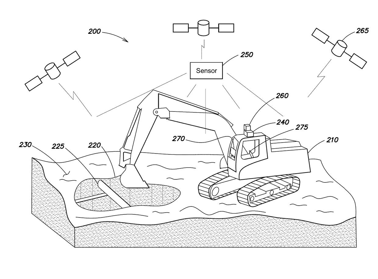
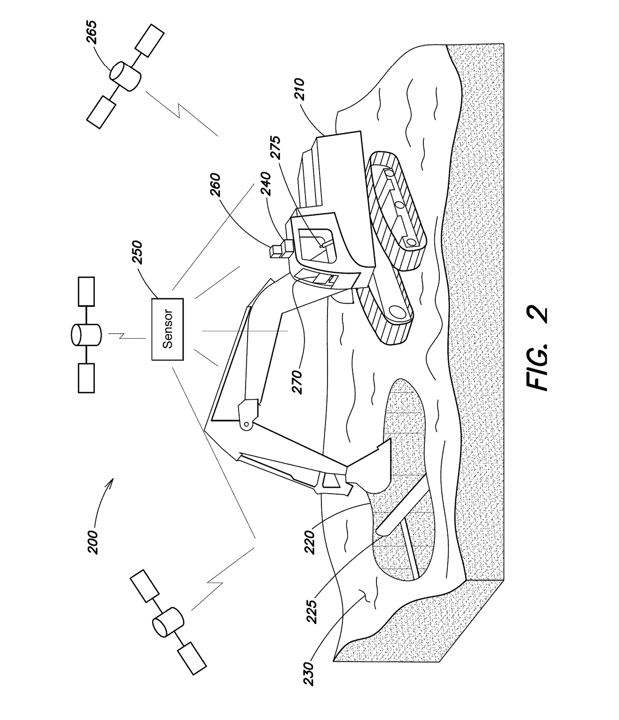
[0020]FIG. 2 is a diagram of an example system 200 for providing augmented reality at a site with a dynamically changing terrain surface. A terrain surface is considered to be dynamically changing if it is subject to continuous or periodic alterations over a period of time. In this example, the terrain surface is dynamically changing as a result of an ongoing excavation 220 by an excavator 210 in the terrain 230. In this example, various subsurface features, such as pipes 225, may be disposed at the site, in the path of the excavation 220 and / or proximate thereto.

[0021]The system may include a camera 240 that captures a view of the site of the excavation 220 used for augmentation. The camera 240 may be a video camera (e.g., a webcam) that captures successive images at a predetermined frame rate. In one implementation, the camera 240 is mounted to the excavator, for example, in the excavator's cab, so that it shares a similar perspective to that of the operator. Alternatively, the ca...


PUM


Abstract

In one embodiment, an augmented view is generated that accounts for dynamically changing terrain surface at a site. A sensor captures live georeferenced terrain surface topography for the site. A camera captures an image of the site. Further, a tracking system determines a georeferenced camera pose of the camera. An augmented reality application aligns a georeferenced three-dimensional (3-D) model for the site with the live georeferenced terrain surface topography. Then, using at least the captured image, the georeferenced camera pose, the georeferenced 3-D model and live georeferenced terrain surface topography, the augmented reality application creates an augmented view of the site that shows graphical representations of subsurface features. At least a portion of the graphical representations are dynamically conformed to the contours of the terrain surface in the image based on the live georeferenced terrain surface topography. The graphical representations may include virtual excavation and / or virtual paint markings.

Description

BACKGROUNDTechnical Field[0001]The present disclosure relates to augmented reality, and more specifically, to techniques for using augmented reality with a dynamically changing terrain surface.Background Information[0002]Excavation is typically a high-risk operation. During excavation, subsurface features (i.e., water pipes, gas pipes, sewer pipes, electrical lines or other below-grade utilities or obstructions) may be struck by excavators causing potentially serious injuries and damage. Any repairs necessitated by the damage may lengthen the disruption caused the by the excavation. For example, if the excavation is part of a road work project and a water pipe is struck and damaged, the time needed to repair the damage may significantly lengthen any traffic disruption already caused by the project, and impose a further burden on local residents and businesses.[0003]One of the main causes of subsurface utilities strikes is uncertainty on behalf of the excavator operator as to the loc...

Claims


Application Information

Patent Timeline
Patent Type & Authority Patents(United States)
IPC IPC(8): G06T17/05G06T17/10E02F9/24G06T19/00
CPCG06T17/05E02F9/245G06T19/006G06T17/10E02F9/261
Inventor COTE, STEPHANELETOURNEAU, IANMARCOUX-OUELLET, JADE
Owner BENTLEY SYST INC
Why Eureka
Try Eureka