
System and method for rate modulated cardiac therapy utilizing a temperature senor

a technology of temperature sensor and cardiac therapy, which is applied in the field of automatic adjustment of the operating parameters of the cardiac rhythm management system, can solve the problems of significant complexity of the apparatus and method without providing any benefit to the exercise response, and achieve the effects of reducing the complexity of the apparatus and method, preventing a prolonged response to non-sustained exercise, and improving the determination of the rate respons

Active Publication Date: 2017-12-05
PACESETTER INC
View PDF12 Cites 5 Cited by
  • Summary
  • Abstract
  • Description
  • Claims
  • Application Information

AI Technical Summary

Benefits of technology

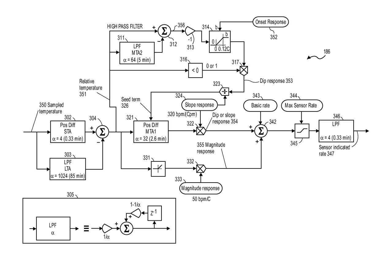
[0008]Certain conventional pacemakers took into account a fourth characteristic of the temperature signal, diurnal temperature variation. This significantly complicated the apparatus and method without providing any benefit to the exercise response. Certain embodiments of the present disclosure eliminate this parameter, reducing calculation complexity and therefore reducing power consumption, which in turn improves pacemaker longevity.
[0009]Although certain conventional pacemakers took into account a temperature dip, they responded with a rate increased by a fixed amount for a fixed time, or with a rate increased in proportion to the magnitude of the dip. Neither response is optimal. The fixed response requires a predetermined threshold for identifying a dip, which in some cases fails to identify a true onset of exercise and in other cases identifies an onset of exercise when none has occurred. The proportional response is inappropriate because the magnitude of the dip is indicative of the state of the patient's peripheral circulation, not of the level of exercise. Certain embodiments of the present disclosure advantageously provide a limited proportional response to a temperature dip, which overcomes the problems of a predetermined threshold, while avoiding over-response to deep dips indicative of poor peripheral circulation.
[0010]Certain embodiments of the present disclosure provide a dip response using a high-pass filter, such that the response diminishes progressively with time after the onset of exercise. This advantageously prevents a prolonged response for non-sustained exercise in a patient whose dip in temperature is prolonged due to poor peripheral circulation.
[0011]According to certain embodiments of the present disclosure, only a positive temperature slope is used to determine a rate response. This advantageously improves the determination of rate response to exercise as the absolute value of negative slope is not indicative of the rate of heat production, i.e. the level of exercise.
[0013]Certain embodiments of the present disclosure advantageously do not take temperature magnitude into account until it becomes positive with respect to the relative temperature, i.e. until the temperature dip due to poor peripheral circulation has dissipated. Instead, according to certain embodiments, temperature slope is used to set the response as the dip dissipates. Advantageously, this approach does not require a second moving baseline constructed from a model intended to fit all patients. It reduces the complexity of the apparatus and method, and it also reduces the number of parameters requiring adjustment to the individual patient.
[0014]Certain embodiments provide a smooth transition in rate response when the temperature begins to climb after the initial dip. According to these embodiments, the slope response is seeded with the dip response in order to prevent an inappropriate decrease in rate response in this transition region, as the dip response decreases before the slope response is established.

Problems solved by technology

This significantly complicated the apparatus and method without providing any benefit to the exercise response.

Method used


Image

  • System and method for rate modulated cardiac therapy utilizing a temperature senor
  • System and method for rate modulated cardiac therapy utilizing a temperature senor
  • System and method for rate modulated cardiac therapy utilizing a temperature senor

Examples


Embodiment Construction

[0038]The invention is described below, with reference to detailed illustrative embodiments. It will be apparent that the invention may be embodied in a wide variety of forms, some of which may appear to be quite different from those of the disclosed embodiments. Consequently, the specific structural and functional details disclosed herein are merely representative and do not limit the scope of the invention. For example, based on the teachings herein one skilled in the art should appreciate that the various structural and functional details disclosed herein may be incorporated in an embodiment independently of any other structural or functional details. Thus, an apparatus may be implemented or a method practiced using any number of the structural or functional details set forth in any disclosed embodiment(s). Also, an apparatus may be implemented or a method practiced using other structural or functional details in addition to or other than the structural or functional details set ...


PUM


Abstract

A cardiac rhythm management system provides an increase in pacing rate as a combination of responses to three characteristics of a relative-temperature signal: a dip, a positive slope, and a positive magnitude. The relative-temperature signal is the difference between a short-term and a long-term temperature average. A dip produces a limited and temporary rate increase having a first proportionality. A positive slope produces a rate increase with a second proportionality. A positive magnitude produces a rate increase with a third proportionality. The dip response seeds the slope response to provide a seamless and immediate rate transition after a dip. The cardiac rhythm management system limits and filters the sum of the rate increases to provide a sensor indicated rate, which is used to stimulate the heart.

Description

PRIORITY[0001]This application claims the benefit of U.S. Provisional Application No. 61 / 993,606 filed May 15, 2014, incorporated herein by reference in its entirety to provide continuity of disclosure.INCORPORATION BY REFERENCE[0002]All publications and patent applications mentioned in this specification are herein incorporated by reference in their entirety to the same extent as if each individual publication or patent application was specifically and individually indicated to be incorporated by reference.FIELD[0003]This disclosure is directed to medical devices and methods for cardiac rhythm management. More specifically, the present invention relates to systems and methods for automatically adjusting the operating parameters of a cardiac rhythm management system.BACKGROUND[0004]Cardiac pacing electrically stimulates the heart when the heart's natural pacemaker and / or conduction system fails to provide synchronized atrial and ventricular contractions at appropriate rates and inte...

Claims


Application Information

Patent Timeline
Patent Type & Authority Patents(United States)
IPC IPC(8): A61N1/365A61N1/375
CPCA61N1/3756A61N1/3655
Inventor CHIN, DONALDFISHLER, MATTHEW G.JACOBSON, PETER M.
Owner PACESETTER INC
Learn More