Pressure detection and display apparatus and electronic device

a display apparatus and pressure detection technology, applied in the direction of instruments, computing, piezoelectric devices, etc., can solve the problem of not being able to visually recognize the display of pressure detection and display apparatus, and achieve the effect of improving the transparency of the entire pressure detection apparatus

Inactive Publication Date: 2017-12-05
NISSHA PRINTING COMPANY
View PDF12 Cites 6 Cited by
  • Summary
  • Abstract
  • Description
  • Claims
  • Application Information

AI Technical Summary

Benefits of technology

[0025]Accordingly, the transparency of the entire pressure detection apparatus is improved.
[0026]According to a pressure detection and display apparatus of the ...

Problems solved by technology

However, in the pressure detection and display apparatuses, when operating the piezoelectric sensor, if a person wears polarized sunglasses, the direction of the absorption axis of the light waves of the polarized sunglasse...

Method used


Image

  • Pressure detection and display apparatus and electronic device
  • Pressure detection and display apparatus and electronic device
  • Pressure detection and display apparatus and electronic device

Examples


first embodiment

[0032]1. First Embodiment

[0033](1) Structure of the pressure detection and display apparatus

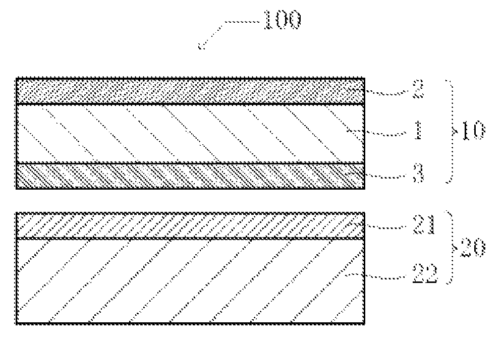
[0034]Referring to FIG. 1, the structure of the pressure detection and display apparatus according to an embodiment of the present invention will be described. FIG. 1 is a cross section of the pressure detection and display apparatus.

[0035]The pressure detection and display apparatus has a function of detecting amount and position of the applied load.

[0036]As shown in FIG. 1, a pressure detection apparatus 100 includes a piezoelectric sensor 10 and a display device 20. The piezoelectric sensor 10 is laminated on the display device 20. The piezoelectric sensor 10 is a device that generates electric charge according to the applied load. The piezoelectric sensor 10 is configured such that a piezoelectric layer 1 is interposed between upper electrode 2 and lower electrode 3. The display device 20 is a device that displays an object on a surface of the piezoelectric sensor 10. The display device 2...

second embodiment

[0060]2. Second Embodiment

[0061]The piezoelectric layer 1 may be patterned so as to have active portions and inactive portions.

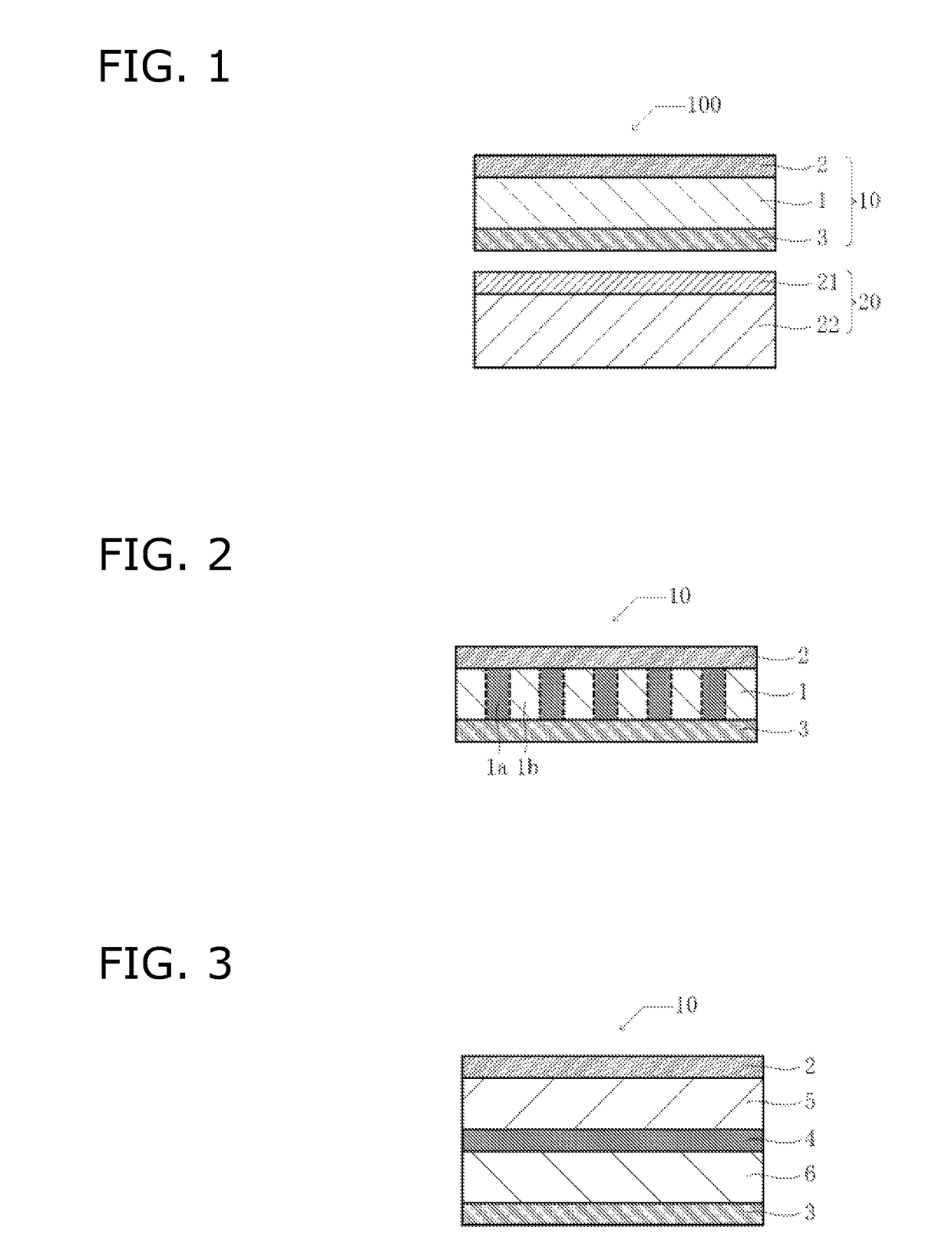
[0062]FIG. 2 is a cross section of the piezoelectric sensor according to the second embodiment.

[0063]As shown in FIG. 2, the piezoelectric layer 1 includes active piezoelectric portions la and inactive piezoelectric portions 1b.

[0064]The active piezoelectric portions 1a are portions where the electrical charge is generated when the load is applied to the piezoelectric sensor 10. In contrast, the inactive piezoelectric portions 1b are portions where the electrical charge is not generated even if the load is applied.

[0065]The above-described configuration prevents the generated electrical charge from leaking around the upper electrode 2 or the lower electrode 3 and mixing into other electrodes (i.e., preventing the cross-talk phenomenon). As a result, it is possible to improve position detection accuracy and load detection accuracy.

third embodiment

[0066]3. Third Embodiment

[0067]Although the configuration in which the piezoelectric layer 1 is interposed between the upper electrode 2 and the lower electrode 3 was described, a reference electrode 4 may be disposed between the upper electrode 2 and the lower electrode 3.

[0068]FIG. 3 is a cross section of the piezoelectric sensor according to the third embodiment.

[0069]As shown in FIG. 3, the piezoelectric sensor 10 of the third embodiment includes a reference electrode 4 between the upper electrode 2 and the lower electrode 3. Between the upper electrode 2 and the reference electrode 4, a first piezoelectric layer 5 is provided. Between the lower electrode 3 and the reference electrode 4, a second piezoelectric layer 6 is provided. Materials of the first piezoelectric layer 5 and the second piezoelectric layer 6 are the same as those of the piezoelectric layer 1. Material of the reference electrode 4 is the same as those of the upper electrode 2 and the lower electrode 3.

[0070]Th...


PUM


Abstract

A pressure detection and display apparatus can provide good visibility even if a person wears polarized sunglasses. The pressure detection and display apparatus includes a piezoelectric sensor having upper electrode, lower electrode, and a piezoelectric layer interposed between the upper electrode and the lower electrode, a polarization plate disposed under the lower electrode, and a display member disposed under the polarization plate. The piezoelectric layer is made of a retardation plate. The piezoelectric sensor and the polarization plate are arranged such that the absorption axis of the piezoelectric layer defines an angle of 20 degrees to 70 degrees relative to the slow phase axis of the polarization plate.

Description

CROSS-REFERENCE TO RELATED APPLICATIONS[0001]This U.S. National stage application claims priority under 35 U.S.C. §119(a) to Japanese Patent Application No. 2013-118300, filed in Japan on Jun. 4, 2013, the entire contents of Japanese Patent Application Nos. 2013-118300 are hereby incorporated herein by reference.BACKGROUND[0002]Field of the Invention[0003]The present invention is related to pressure detection and display apparatuses and electronic devices.[0004]Background Information[0005]Piezoelectric sensors have been known which utilize a piezoelectric layer to detect the applied load. For example, in Japanese Patent Publication 2004-125571, a transparent piezoelectric sensor including a transparent pressure sensitive layer and a pair of transparent conductive layers is disclosed. Recently, it has been attempted to manufacture pressure detection and display apparatuses by combining a transparent piezoelectric sensor and a display device (mainly, a liquid crystal panel or an organ...

Claims


Application Information

Patent Timeline
IPC IPC(8): G01L1/16G01L9/08G06F3/041G06F3/044G02F1/1333
CPCG06F3/044G01L1/16G01L9/08G06F3/0412G06F3/0414G06F2203/04105G02F1/13338G02F2001/133394G06F2203/04103G02F1/133394
Inventor WATAZU, YUJI
Owner NISSHA PRINTING COMPANY
Why Eureka
Try Eureka