Anamorphic objective zoom lens

a zoom lens and anamorphic technology, applied in the field of anamorphic objective zoom lenses, can solve the problems of large diameter, corresponding potentially higher weight and cost, and the full aperture may be relatively slow as compared, and achieve the effects of reducing the degree of aberration correction, reducing the residual lateral chromatic aberration, and reducing the degree of aberration

Active Publication Date: 2017-12-12
TAYLOR-HOBSON
View PDF10 Cites 0 Cited by
  • Summary
  • Abstract
  • Description
  • Claims
  • Application Information

AI Technical Summary

Benefits of technology

[0017]The present invention relates to an anamorphic objective zoom lens including, along an optical axis and in order from an object space to an image space, at least a negative (−) power spherical first lens group: an anamorphic second lens group, a spherical third lens group preferably having a positive (+) power, a variable power spherical zoom fourth lens group and a positive (+) power spherical fifth lens group wherein an aperture stop is located before, after or preferably within the spherical fifth power lens group. The anamorphic second lens group has at least one cylindrical surface in a first direction and at least one other cylindrical surface in a substantially perpendicular direction to the first direction to enable a high degree of aberration correction over the whole image, whereby the residual longitudinal chromatic aberration and the residual lateral chromatic aberration are substantially reduced. The variable power spherical fourth lens group has at least two lens sub groups that are axially movable to provide zooming. The negative power spherical first lens group may provide focusing by movement of at least one of the lens elements contained therein and may exhibit low breathing in the focus range. Lens elements of the spherical third and fifth lens groups are independently axially movable by active or passive or active and passive means while preferably maintaining the overall length of the anamorphic objective zoom lens to provide thermal compensation of defocus which is consistently small and has little astigmatism through focusing and zooming. The lens is a complete assembly that forms a real image.
[0018]The anamorphic second lens group provides a squeeze of the field of view so that the focal lengths in the X and Y directions are different by a ratio of about two times which is typical for traditional anamorphic optical systems. The positive power spherical fifth lens group adjacent the image space delivers the radiation passing through the optical system on to the image sensor with nearly telecentric light paths and suitably high relative illumination, thereby increasing the efficiency of many electronic sensors.
[0020]The lens elements of the spherical third and fifth lens groups which provide thermal compensation of defocus through focusing and zooming can be independently axially moved by active means employing motors or passive means utilizing materials exhibiting suitable thermal expansion coefficients in the mechanical support of the lens elements or a combination of both means. The thermal compensation of defocus by active, passive or combined means has the additional advantage of not requiring the operator of the lens to refocus the lens and the associated loss of focus scale calibration. The thermal compensation of defocus by passive means has the additional advantage of not requiring the complexity of a power source for motors.
[0029]The anamorphic objective zoom lens provides low residual chromatic aberration, a traditional oval bokeh shape, and different depths of field in the vertical and horizontal azimuth directions of the field.

Problems solved by technology

Another common drawback with this anamorphic objective zoom lens arrangement is that the full aperture may be relatively slow as compared to that of anamorphic prime lenses.
This anamorphic objective zoom lens arrangement produces images having oval or elliptically shaped out of focus objects commonly referred to as the bokeh which is desired by cinematographers for the reasons previously given however these lenses normally provide only small zoom ratios of 2× or 3×, where the smaller zoom ratio provides the widest field of view, and they tend be large in diameter with corresponding potentially higher weight and cost.
Many of the less desired residual optical aberrations and characteristics of these front and rear anamorphic objective zoom lens arrangements were accepted by cinematographers with film based cameras but with the advent and adoption of electronic sensor based digital cameras some of them have become less acceptable.
Improving the optical aberrations and characteristics of anamorphic objective zoom lenses of this arrangement may involve increasing optical surface shape complexity and hence manufacturing cost including adding aspherical and free-form shaped optical surfaces.
Lenses of this type tend to be sensitive to changes in temperature and will go out of focus without some means of compensating for temperature shifts.

Method used


Image

  • Anamorphic objective zoom lens
  • Anamorphic objective zoom lens
  • Anamorphic objective zoom lens

Examples


Embodiment Construction

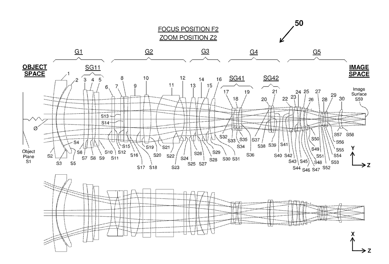
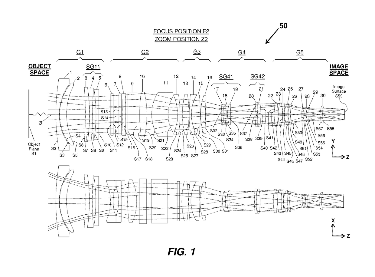
[0044]The invention relates to anamorphic objective zoom lenses, and in particular to a range of different focal length anamorphic objective zoom lenses covering at least a focal length range from 35 mm to 140 mm and preferably 40 mm to 125 mm in the Y direction and providing low residual chromatic aberration, a traditional oval bokeh shape and different depths of field in the vertical and horizontal azimuth directions of the field.

[0045]The term “lens group” as used in connection with the anamorphic objective zoom lens disclosed herein means one or more individual lens elements. Also, the terms “optical stop” and “stop” are equivalent terms that can be used interchangeably.

[0046]The example provided herein is a preferred embodiment of the invention in which the first (front) lens group is negatively powered, the third lens group is positively powered, the fourth lens group is variable powered and the last (rear) lens group is positively powered. Those lens groups are paired with an...


PUM


Abstract

The anamorphic objective zoom lens includes, along an optical axis and in order from an object space to an image space: at least a negative (−) power spherical first lens group; an anamorphic second lens group, spherical third lens group preferably having positive (+) power, a variable power spherical fourth lens group and a positive (+) power spherical fifth lens group. The aperture stop is located before, after or preferably within the spherical fifth lens group. All spherical lens groups contain spherical and piano refractive optical surfaces. The anamorphic second lens group contains cylindrical and plano optical surfaces with at least one cylindrical surface oriented at substantially 90 degrees about at least one other cylindrical surface. The spherical first lens group may provide focusing. The variable power spherical fourth lens group provides zooming. The spherical third and fifth lens groups may provide compensation for thermal defocus.

Description

CROSS-REFERENCE TO RELATED APPLICATIONS[0001]This application is a continuation in part of copending application Ser. No. 14 / 683,297 filed Apr. 10, 2015, which is a continuation is part of copending application Ser. No. 14 / 218,064, filed Mar. 18, 2014, which application claims the benefit under 37 CFR §119(e) of U.S. Provisional Application No. 61 / 808,343 filed Apr. 4, 2013, the contents of which are incorporated herein their entirety.STATEMENT REGARDING FEDERALLY SPONSORED RESEARCH OR DEVELOPMENT[0002]Not ApplicableREFERENCE TO A “SEQUENCE LISTING”, A TABLE, OR A COMPUTER PROGRAM LISTING APPENDIX SUBMITTED ON COMPACT DISC[0003]Not ApplicableBACKGROUND OF THE INVENTION[0004]1. Field of the Invention[0005]The present invention relates to anamorphic objective zoom lenses, and more particularly to a range of different focal length anamorphic objective zoom lenses with zoom ratios that provide imaging over wide to narrow fields of view and provide traditional anamorphic imaging characte...

Claims


Application Information

Patent Timeline
Patent Type & Authority Patents(United States)
IPC IPC(8): G02B15/14G02B3/06G02B13/18G02B15/177G02B27/00G02B7/02G02B15/16G02B13/00G02B3/04G02B13/08G02B15/20
CPCG02B7/028G02B15/177G02B27/0025G02B3/06G02B13/0045G02B13/08G02B13/18G02B15/14G02B15/16G02B15/20G02B13/009G02B3/04G02B13/002G02B15/1455
Inventor NEIL, IAIN A.
Owner TAYLOR-HOBSON
Why Eureka
Try Eureka