Eureka AIR delivers breakthrough ideas for toughest innovation challenges, trusted by R&D personnel around the world.

Apparatus for remotely lifting a buried explosive device

Inactive Publication Date: 2017-12-19
THE UNITED STATES OF AMERICA AS REPRESENTED BY THE SECRETARY OF THE NAVY
View PDF24 Cites 0 Cited by
  • Summary
  • Abstract
  • Description
  • Claims
  • Application Information

AI Technical Summary

Benefits of technology

The invention provides an apparatus for lifting a buried explosive device. The design allows for safe and efficient operation while minimizing pack space. The apparatus can also be configured in different ways to better suit the needs of EOD operators.

Problems solved by technology

This requirement may arise because the EOD work area is not easily accessible to vehicles or because vehicles are not available or for other reasons.
These methods have a high risk of injury or death to the OED personnel.
Many devices are known for lifting objects remotely from the ground, but most of the known devices are large and heavy and are not man-portable by one person.
First, a portion of the explosive device is manually uncovered.
In the case of an explosive device weighing up to 400 pounds, the conventional devices mechanically fail and do not lift the explosive device out of the ground.

Method used


Image

  • Apparatus for remotely lifting a buried explosive device
  • Apparatus for remotely lifting a buried explosive device
  • Apparatus for remotely lifting a buried explosive device

Examples


Embodiment Construction

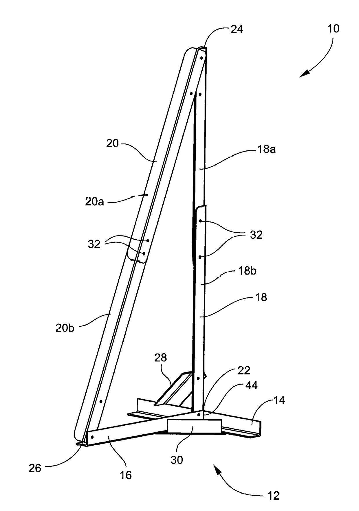
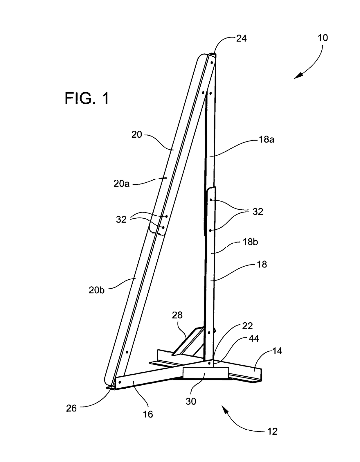
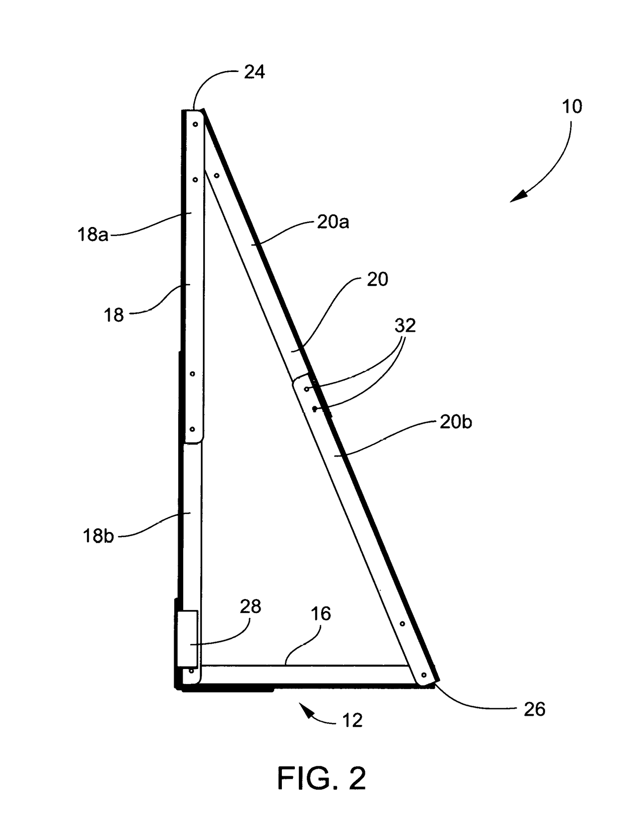
[0020]Referring to FIGS. 1-6, an apparatus 10 for removing a buried explosive device 42 (FIG. 7) includes a T-shaped base 12 having a flange member 14 and a web member 16. The web member 16 has one (first) end 22 fixed at a right angle to the midpoint 44 of the flange member 14 to form the T-shaped base 12. A vertical upright member 18 is fixed at one (first) end to the midpoint 44 of the flange member 14 and is normal to the plane of the T-shaped base 12. The vertical upright member 18 has a second end 24 that is distal the T-shaped base 12. A diagonal member 20 has a first end fixed to the second end 24 of the vertical upright member 18 and is fixed at its second end to a second end 26 of the web member 16 that is distal the flange member 14.

[0021]In an exemplary embodiment, the vertical upright member 18 is at least twice the length of the web member 16. Particularly, the vertical upright member 18 is about 2.3 times the length of the web member 16. The flange member 14 may be ab...


PUM


Abstract

An apparatus for lifting a buried explosive device includes a T-shaped base including a flange member and a web member. The web member has one end fixed at a right angle to the midpoint of the flange member. A vertical upright member is fixed at one end to the midpoint of the flange member. A diagonal member is fixed at one end to the other end of the vertical upright member and fixed at another end to a second end of the web member that is distal the flange member. The vertical upright member is at least twice a length of the web member. The flange member, the web member, the vertical upright member and the diagonal member are L-channel members made of carbon fiber.

Description

STATEMENT OF GOVERNMENT INTEREST[0001]The invention described herein may be manufactured and used by or for the Government of the United States of America for Governmental purposes without the payment of any royalties thereon or therefor.FIELD OF THE INVENTION[0002]The invention relates in general to explosive ordnance disposal, and in particular to the removal of explosive devices that are buried in the ground.BACKGROUND OF THE INVENTION[0003]Explosive ordnance disposal (EOD) personnel (operators) are often required to carry the necessary EOD tools on their person for a long distance. This requirement may arise because the EOD work area is not easily accessible to vehicles or because vehicles are not available or for other reasons. In any event, the EOD tools and equipment must be small in size (or easily disassembled into a small size) and small in weight to enable carriage by an EOD operator.[0004]In the case of buried explosive threats, the EOD operator often removes the explosi...

Claims


Application Information

Patent Timeline
IPC IPC(8): B66F19/00B66C1/34F41H11/12B66F11/00F16M11/20
CPCB66F19/00B66C1/34F41H11/12B66F11/00F16M11/2014B66F15/00
Inventor WADE, JAMESGEBSTADT, MATTHEWSHARP, MIKEFOLTZ, LEEDIAZ, ANGEL
Owner THE UNITED STATES OF AMERICA AS REPRESENTED BY THE SECRETARY OF THE NAVY
Why Eureka
Eureka Blog
Learn More