Limited entry phased perforating gun system and method

a perforating gun and limited entry technology, applied in the field of perforation guns, can solve the problems of high tortuosity in the flow path, significant pressure drop, pressure loss, etc., and achieve the effect of efficient oil and gas flow rate during production

Active Publication Date: 2017-12-19
WELLS FARGO BANK NAT ASSOC +1
View PDF35 Cites 24 Cited by
  • Summary
  • Abstract
  • Description
  • Claims
  • Application Information

AI Technical Summary

Benefits of technology

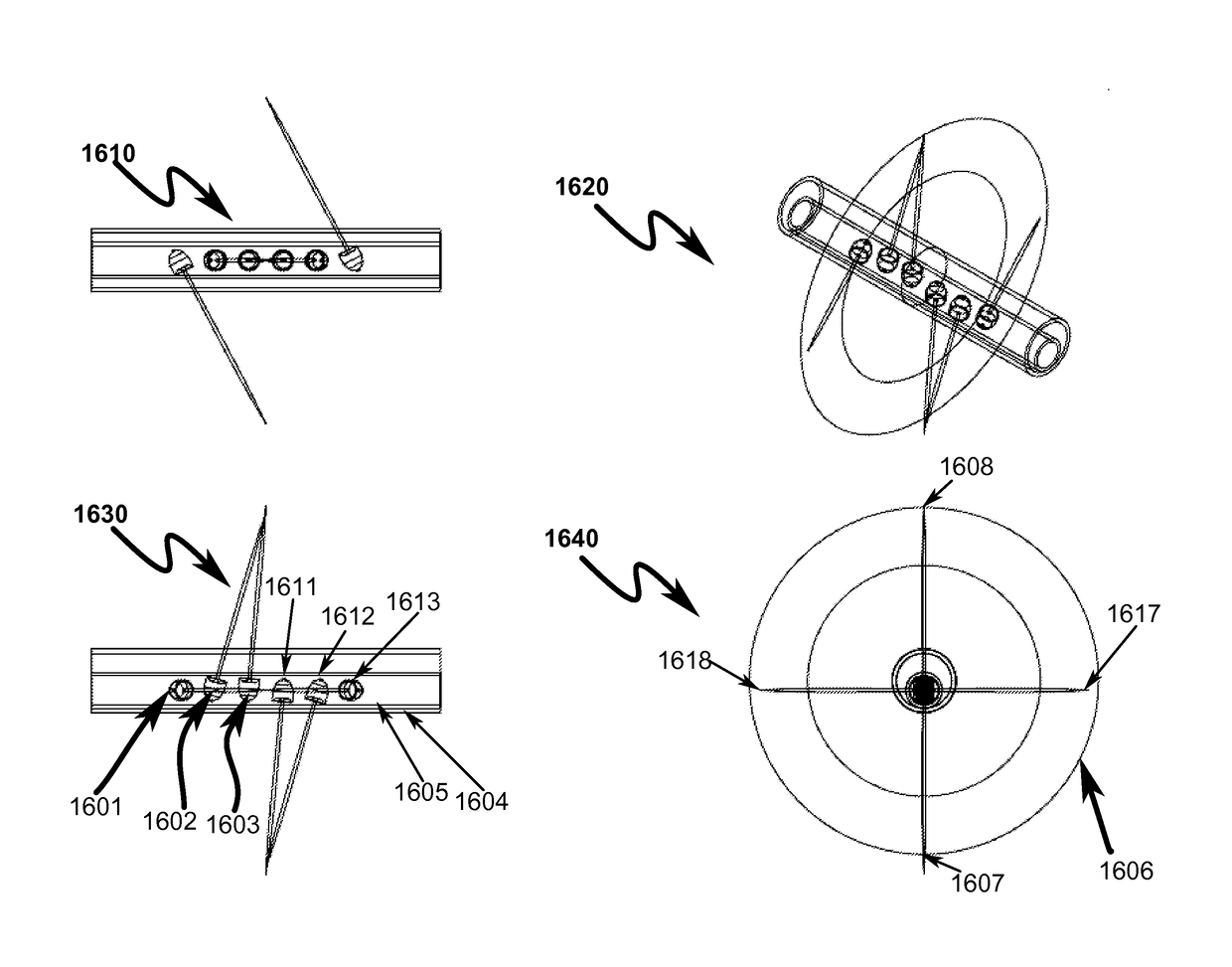
[0030]Provide for minimizing multiple fracture initiations within a fracture stage.
[0033]Provide for efficiently reducing tortuosity, energy loss and pressure loss in a perforation tunnel.
[0035]Provide for perforating more zones with less number of perforations in each cluster for increasing wellbore production efficiency.

Problems solved by technology

Misalignment between the preferred fracture plane and perforations in a well can result in significant pressure drop due to tortuosity in the flow path near the wellbore.
The perforations that are phased at 90 degrees to the preferred fracture plane create pinch points resulting in pressure loss and high tortuosity in the flow path.
Therefore, if any perforation does not participate, then the incremental rate per perforation of every other perforation is increased, resulting in higher perforation friction.
If all perforations are involved, and the perforations are shot with 60°, 90°, or 120° phasing, multiple fracture planes may be created, leading to substantial near wellbore friction and difficulty in placing the planned fracturing treatment.
Some of the perforation tunnels cause energy and pressure loss during fracturing treatment which reduces the intended pressure in the fracture tunnels.
The prior art as detailed above suffers from the following deficiencies:Prior art systems do not provide for minimizing multiple fracture initiations within a fracture stage.Prior art systems do not provide for 2 or 4 orienting shaped charges in a cluster that intersect at a preferred fracturing plane when perforated.Prior art systems do not provide for orienting shaped charges with an internal swivel.Prior art systems do not provide for efficiently reducing tortuosity and energy loss in a perforation tunnel.Prior art systems do not provide for radially extended longer fractures in a preferred perforation plane.Prior art systems do not provide for perforating more zones with less number of perforations in each cluster for increasing wellbore production efficiency.Prior art systems do not provide a system to fracture into a preferred fracture initiation point in a preferred fracture plane.
While some of the prior art may teach some solutions to several of these problems, the core issue of reacting to unsafe gun pressure has not been addressed by prior art.

Method used


Image

  • Limited entry phased perforating gun system and method
  • Limited entry phased perforating gun system and method
  • Limited entry phased perforating gun system and method

Examples


Embodiment Construction

[0076]While this invention is susceptible of embodiment in many different forms, there is shown in the drawings and will herein be described in detailed preferred embodiment of the invention with the understanding that the present disclosure is to be considered as an exemplification of the principles of the invention and is not intended to limit the broad aspect of the invention to the embodiment illustrated.

[0077]The numerous innovative teachings of the present application will be described with particular reference to the presently preferred embodiment, wherein these innovative teachings are advantageously applied to the particular problems of a limited entry phasing perforating gun system and method. However, it should be understood that this embodiment is only one example of the many advantageous uses of the innovative teachings herein. In general, statements made in the specification of the present application do not necessarily limit any of the various claimed inventions. More...


PUM


Abstract

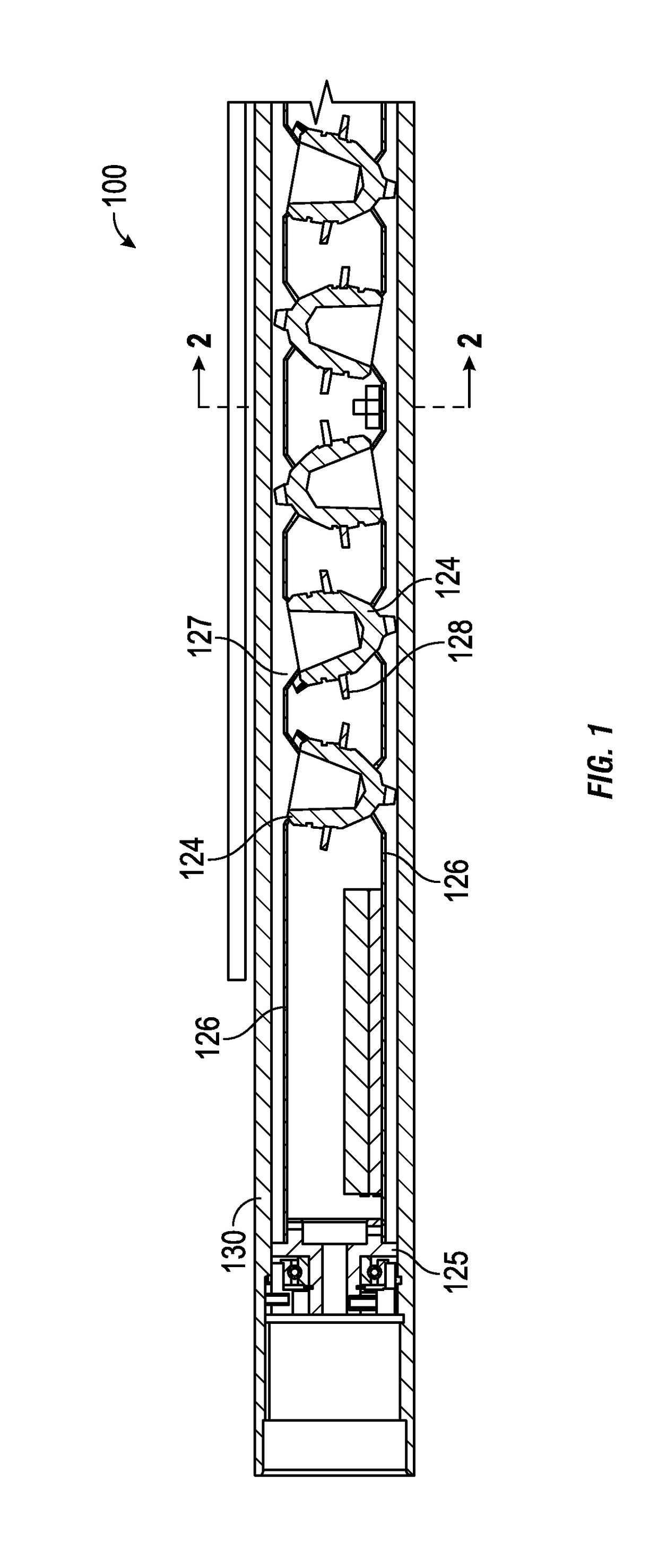
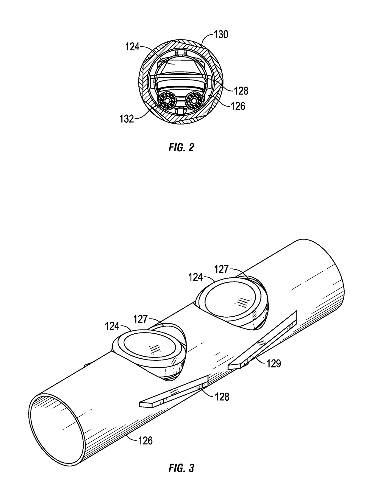
A limited entry perforating phased gun system and method for accurate perforation in a deviated / horizontal wellbore is disclosed. The system / method includes a gun string assembly (GSA) deployed in a wellbore with shaped charge clusters. The charges are spaced and angled such that, when perforated, they intersect at a preferred fracturing plane. Upon fracturing, the fractures initiate at least principal stress location in a preferred fracturing plane perpendicular to the wellbore from an upward and downward location of the wellbore. Thereafter, the fractures connect radially about the wellbore in the preferred fracturing plane. The fracture treatment in the preferred fracturing plane creates minimal tortuosity paths for longer extension of fractures that enables efficient oil and gas flow rates during production.

Description

CROSS REFERENCE TO RELATED APPLICATIONS[0001]This application is a continuation in part and claims priority to U.S. continuation in part patent application Ser. No. 14 / 598,868, filed Jan. 16, 2015, now U.S. Pat. No. 9,562,421, and is a continuation in part application of U.S. nonprovisional patent application Ser. No. 14 / 176,056, filed Feb. 8, 2014, now U.S. Pat. No. 9,038,521, which are all hereby incorporated by reference in their entirety as examples.PARTIAL WAIVER OF COPYRIGHT[0002]All of the material in this patent application is subject to copyright protection under the copyright laws of the United States and of other countries. As of the first effective filing date of the present application, this material is protected as unpublished material.[0003]However, permission to copy this material is hereby granted to the extent that the copyright owner has no objection to the facsimile reproduction by anyone of the patent documentation or patent disclosure, as it appears in the Unit...

Claims


Application Information

Patent Timeline
Patent Type & Authority Patents(United States)
IPC IPC(8): E21B43/117E21B43/119
CPCE21B43/119E21B43/117
Inventor HARDESTY, JOHN T.ROLLINS, JAMES A.
Owner WELLS FARGO BANK NAT ASSOC
Why Eureka
Try Eureka