
Synchronous condenser

a condenser and synchronous technology, applied in the direction of dynamo-electric components, mechanical energy handling, ac network circuit arrangements, etc., can solve the problems of time-consuming and insufficient space and power, and attaching the starting motor to the shaft,

Active Publication Date: 2017-12-19
GE INFRASTRUCTURE TECH INT LLC
View PDF30 Cites 3 Cited by
  • Summary
  • Abstract
  • Description
  • Claims
  • Application Information

AI Technical Summary

Problems solved by technology

Attaching the starting motor to the shaft, however, may be time consuming.
A sufficient amount of space and power also may be required to position and drive the starting motor or other device used to rotate the shaft.

Method used


Image

  • Synchronous condenser
  • Synchronous condenser
  • Synchronous condenser

Examples


Embodiment Construction

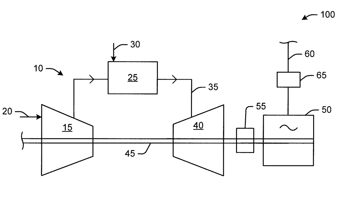
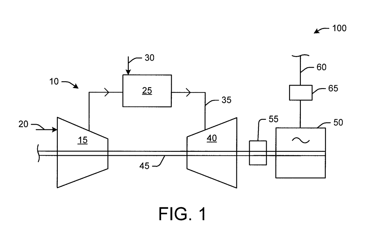
[0011]Referring now to the drawings, in which like numerals refer to like elements throughout the several views, FIG. 1 shows a schematic diagram of gas turbine engine 10 as may be used herein. The gas turbine engine 10 may include a compressor 15. The compressor 15 compresses an incoming flow of air 20. The compressor 15 delivers the compressed flow of air 20 to a combustor 25. The combustor 25 mixes the compressed flow of air 20 with a pressurized flow of fuel 30 and ignites the mixture to create a flow of combustion gases 35. Although only a single combustor 25 is shown, the gas turbine engine 10 may include any number of the combustors 25 arranged in a circumferential array or otherwise. The flow of combustion gases 35 is delivered in turn to a turbine 40. The flow of combustion gases 35 drives the turbine 40 so as to produce mechanical work. The mechanical work produced in the turbine 40 drives the compressor 15 via a shaft 45 and an external load such as an electrical generato...


PUM


Abstract

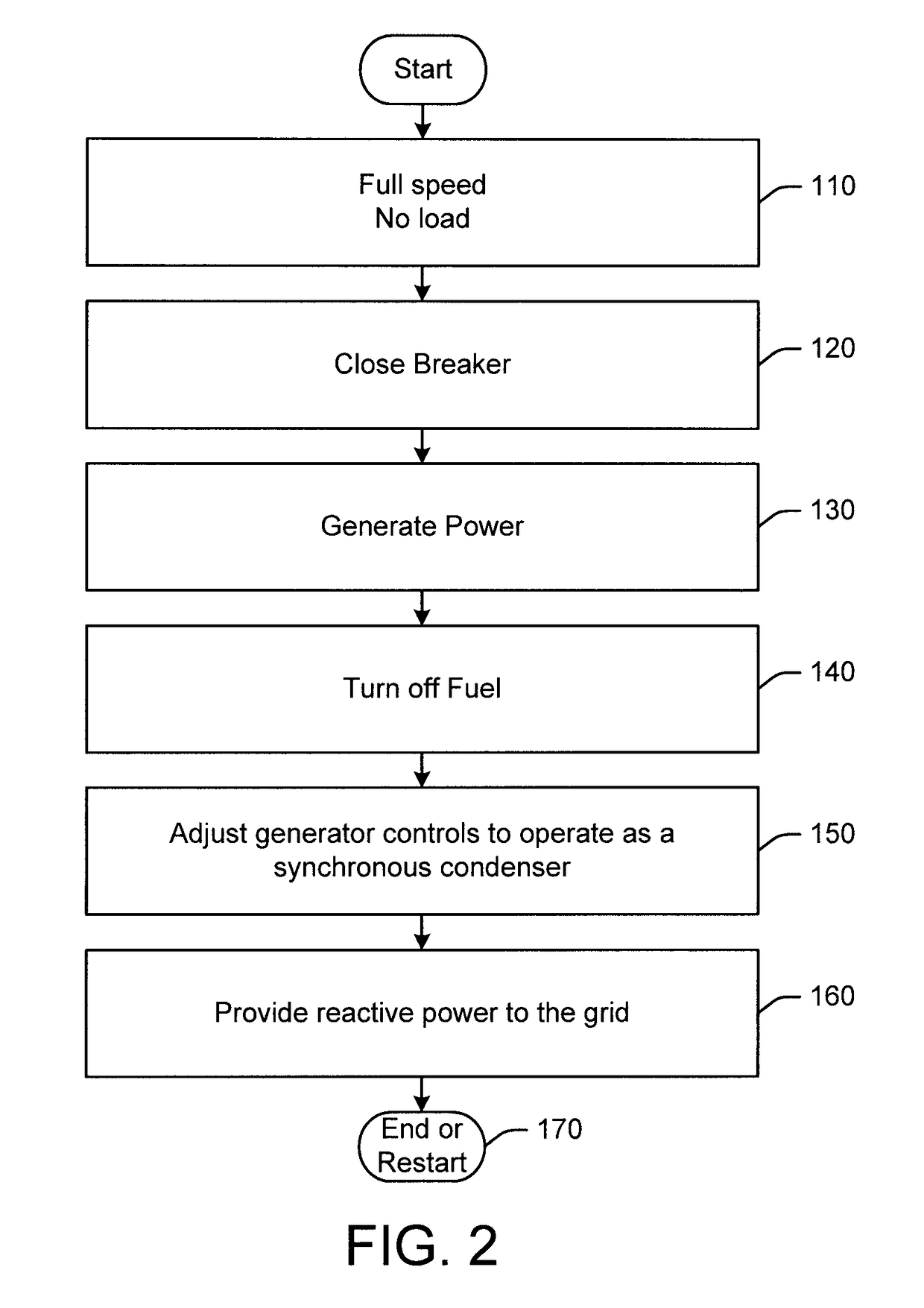
The present application thus provides a method of operating a synchronous condenser. The method may include the steps of accelerating a gas turbine engine to full speed no load conditions, connecting a generator attached to the gas turbine engine to an electric power grid, turning off a flow of fuel to the gas turbine engine, operating the generator in a synchronous condenser mode, and providing or absorbing reactive power to or from the electric power grid.

Description

TECHNICAL FIELD[0001]The present application and the resultant patent relate generally to gas turbine engines and more particularly relate to a synchronous condenser attached to a gas turbine engine to provide electric power grid stability without further mechanical and / or electrical components.BACKGROUND OF THE INVENTION[0002]Synchronous condensers are utilized in a wide variety of applications such as power generation. Synchronous condensers typically are utilized to adjust conditions on an electric power distribution grid. A synchronous condenser is a specialized motor with an unattached shaft that spins freely. The synchronous condenser may generate or absorb reactive power as needed to support the voltage and / or maintain a power factor on the electric power distribution grid.[0003]Similarly, synchronous generators driven by turbines or other types of power sources are commonly used by utilities to produce electrical energy. After years of use, a power utility may retire or deco...

Claims


Application Information

Patent Timeline
Patent Type & Authority Patents(United States)
IPC IPC(8): H02J3/18H02K7/118H02K7/18
CPCH02J3/1885H02K7/1823H02K7/118Y02E40/32Y02E40/30
Inventor DAY, SCOTT ARTHUR
Owner GE INFRASTRUCTURE TECH INT LLC
Learn More