
System and method for synchronous control of synthetic test of high-voltage electrical apparatuses

A technology of synthetic test and synchronous control, applied in general control system, control/regulation system, computer control, etc., can solve the problems of control accuracy influence, test failure, large difference between the zero point of current prediction and the real value, etc., to ensure the accuracy , the effect of improving adaptability and improving synchronicity

Active Publication Date: 2014-03-26
XIAN HIGH VOLTAGE APP RES INST CO LTD
View PDF3 Cites 1 Cited by
  • Summary
  • Abstract
  • Description
  • Claims
  • Application Information

AI Technical Summary

Problems solved by technology

[0003] With the development of the high-voltage electrical appliance industry, both large and small currents will appear in the test. Due to the specification limitation of the synchronous control device, when the current amplitude changes greatly beyond its control range, it will inevitably affect the control accuracy; at the same time, the existing technology The synchronous control system in the system can only collect and control a single signal. With the continuous improvement of high-voltage electrical synthesis test technology requirements, especially in the large-capacity synthesis test of high-voltage electrical equipment, simultaneous acquisition and control of multiple parameters is required. Existing equipment and technology cannot fully meet the needs of current experiments
[0004] In the existing synchronous control method, when the main circuit has a DC component, all subsequent current prediction values ​​are predicted by the actual value of the first half-wave current sampling, so the error of the current prediction value will gradually accumulate, making the current prediction zero point The difference from the real value is large, which can easily cause the failure of related experiments

Method used


Image

  • System and method for synchronous control of synthetic test of high-voltage electrical apparatuses
  • System and method for synchronous control of synthetic test of high-voltage electrical apparatuses
  • System and method for synchronous control of synthetic test of high-voltage electrical apparatuses

Examples


Embodiment Construction

[0045] The present invention will be further described in detail below in conjunction with specific embodiments, which are explanations of the present invention rather than limitations.

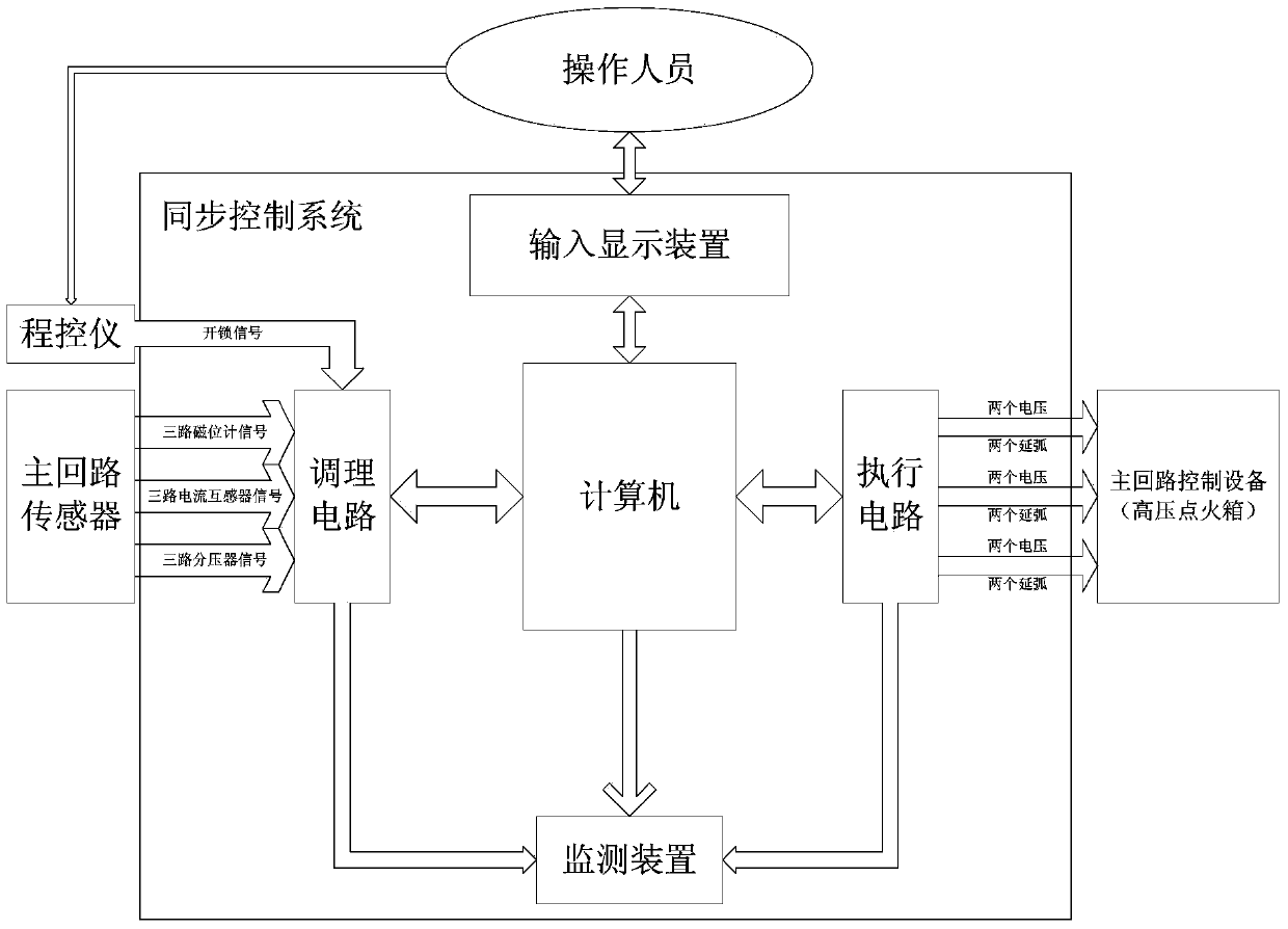
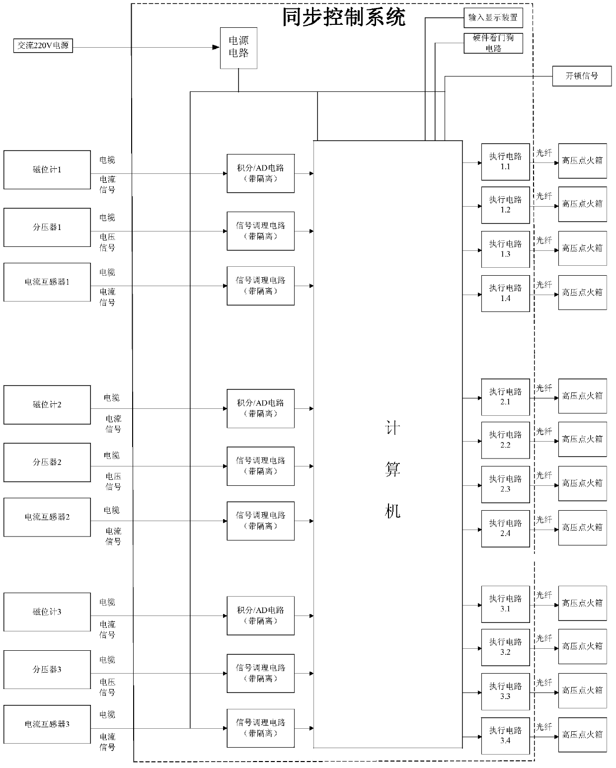
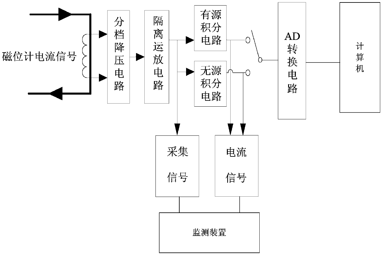
[0046] Such as figure 1 As shown, the synchronous control system of the synthetic test of the high-voltage electrical apparatus of the present invention includes a power supply circuit for supplying power to the system, a sensor signal detection circuit for receiving voltage and / or current signals collected by the sensor in the synthetic test, and a sensor signal detection circuit for converting the input signal Conditioning circuit converted into digital signal, computer used to process digital signal and output control signal, executive circuit used to receive control signal and output corresponding ignition electric signal, input display device used to input and display synthetic test control parameters; sensor The signal detection circuit includes a magnetometer current signal detection c...


PUM


Abstract

The invention relates to a system for synchronous control of synthetic test of high-voltage electrical apparatuses. The system comprises a power circuit, a sensor signal detection circuit, a conditioning circuit, a computer, an execution circuit and an input display device. The power circuit is used for supplying power to the system, the sensor signal detection circuit is used for receiving voltage and / or current signals acquired by sensors in synthetic test, the conditioning circuit is used for converting input signals into digital signals, the computer is used for processing the digital signals and outputting control signals, the execution circuit is used for receiving the control signals and outputting corresponding electric ignition signals, and the input display device is used for inputting and displaying synthetic test control parameters. The invention further provides a corresponding method for synchronous control. Various requirements on the synthetic test of the high-voltage electrical apparatuses can be met, error of current prediction zero is reduced, and success rate of the synthetic test is increased; the input signals of computer access processing are selected according to modes of the synthetic test, and a corresponding control signal output step is executed; the input signals include of one or combinations of more of magnetic potentiometer current signals, potentiometer voltage signals and current transformer current signals.

Description

technical field [0001] The invention relates to the technical field of high-voltage electrical appliance testing, in particular to a synchronous control system and a synchronous control method for high-voltage electrical appliance synthesis testing. Background technique [0002] The synthesis test is an important part of the test detection and test technology research of high-voltage electrical products, and the synchronous control device is an indispensable time control device in the synthesis circuit, an important part of the control system, and the most stringent time requirement in the test. device, so the performance of the synchronous control device is directly related to the success of the synthesis test. [0003] With the development of the high-voltage electrical appliance industry, both large and small currents will appear in the test. Due to the specification limitation of the synchronous control device, when the current amplitude changes greatly beyond its contro...

Claims


Application Information

Patent Timeline
IPC IPC(8): G05B15/02
Inventor 高飞
Owner XIAN HIGH VOLTAGE APP RES INST CO LTD
Learn More