Method for producing a connecting part using an injection foam molding process

a technology of injection foam and molding process, which is applied in the direction of mechanical equipment, transportation and packaging, other domestic objects, etc., can solve the problems of insufficient chemical, thermal adhesive bond, risk, and the separation of the fastening part and the supporting part from one another, and achieves low equipment complexity and efficient and reliable production.

Active Publication Date: 2017-12-26
GOTTLIEB BINDER
View PDF25 Cites 1 Cited by
  • Summary
  • Abstract
  • Description
  • Claims
  • Application Information

AI Technical Summary

Benefits of technology

[0005]An object of the invention is to provide an improved method, with which connecting parts, in which the support part contains the fastening part as an integrated component, can be efficiently and reliably produced with low equipment complexity.

Problems solved by technology

Apart from the environmental impact associated with solvent-containing substances, neither the chemical, nor the thermal adhesive bonds are satisfactory.
As has been shown, when used in floor mats in motor vehicles, a risk exists that the fastening part and the support part will become detached from one another when the temperature and / or the relative humidity in the vehicle is too high.
Another risk is detachment when the floor mat has been used for an extended period of time.
This detachment constitutes a safety risk, in particular, when the floor mat on the driver's side slides forward towards the pedals while driving.
That sliding can lead to uncertainty on the part of the driver and may possibly result in an accident.
Although in this procedure, there is practically no risk of detachment, the number of hooks that can be formed in the injection mold in which the support part is molded is nevertheless extremely limited, for example to a number not exceeding 50 hooks per cm2.
Such a limited achievable packing density of the hooking elements is not satisfactory.
To eliminate this risk, a correspondingly complex design of the injection mold is necessary, for example, to avoid longer flow paths and the increased injection pressures that such a flow path requires.

Method used


Image

  • Method for producing a connecting part using an injection foam molding process
  • Method for producing a connecting part using an injection foam molding process
  • Method for producing a connecting part using an injection foam molding process

Examples


Embodiment Construction

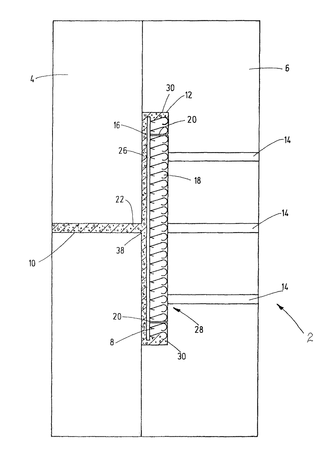
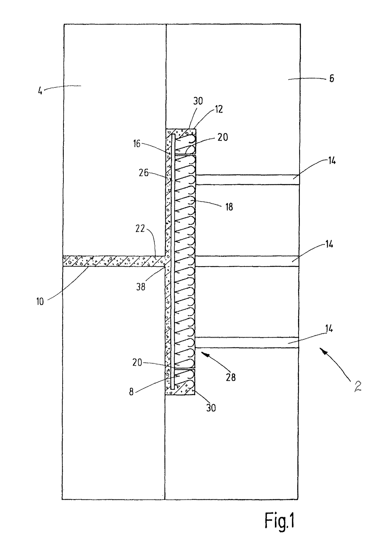
[0028]FIG. 1 shows a highly schematically simplified injection mold 2 in the manner of a schematic diagram. The movable mold parts 4 and 6 of the injection mold 2 delimit a mold cavity 8 in a closed position of the mold parts. From among a plurality of hot runners located in the mold part 4 for supplying the casting material, only one runner 10, is visible in FIG. 1. Air channels 14 leading into the cavity 8 are formed in the mold part 6, which is disposed opposite the mold part 4 having the runner 10. A recess 12 is formed in mold part 16 to create the cavity 8. To carry out an injection foam molding process, an insert part 16 is inserted into the recess 12. The insert part 16 forms the fastening part when the connecting part is finished. The fastening part has the adhesive and / or hooking elements. Before inserting the prefabricated insert part 16 into the injection mold 2, the side of the insert part 16 facing away from the hooking elements 18 is provided with a coating. The coati...


PUM

PropertyMeasurementUnit
pressuresaaaaaaaaaa
adhesiveaaaaaaaaaa
thermal adhesiveaaaaaaaaaa

Abstract

A method for producing a connecting part (28) uses an injection foam molding process. In a first step, a fastening part with adhesive and/or hooking elements (18), forming a component of a contact fastener, is produced and introduced into an injection mold (2) as an insert part (16). A support part (26) is formed in the mold in a second step using a foamed synthetic material (22). The support part is connected to the insert part to form the connecting part (28).

Description

FIELD OF THE INVENTION[0001]The invention relates to a method for producing a connecting part using an injection foam molding process, preferably using a synthetic material. The invention specifically relates to the production of a connecting part, which has, on one side, a fastening part having adhesive and / or hooking elements. The fastening part forms a component of a contact fastener. The connecting part may be part of a fastening system, in which system attachment parts are provided to form a contact fastener connection to a component that is to be connected. The attachment parts have adhesive and / or hooking elements, which can be releasably engaged with the corresponding adhesive and / or hooking elements of the respective connecting part.BACKGROUND OF THE INVENTION[0002]Contact fastener connections are used in many areas to fasten objects or components such that they can be detached again. In motor vehicles, to prevent the mats from slipping or lifting up, the mats are frequentl...

Claims


Application Information

Patent Timeline
Patent Type & Authority Patents(United States)
IPC IPC(8): B29C45/26B60N3/04F16B11/00B29C45/00A44B18/00B29C45/14A44B13/00B29C44/12B29K77/00B29K79/00B29K101/12B29K105/04B29L31/00
CPCB29C45/26A44B13/0052A44B18/008A44B18/0076B29C44/1271B29C45/0025B60N3/046F16B11/006B29C45/14786B29L2031/729B29K2077/00B29K2079/08B29K2101/12B29K2105/04
Inventor POULAKIS, KONSTANTINOS
Owner GOTTLIEB BINDER
Why Eureka
Try Eureka