Unlock instant, AI-driven research and patent intelligence for your innovation.

Reduction of coking in FCCU feed zone

a coke and feed zone technology, applied in the field of coke reduction in fccu feed zone, can solve the problems of unit shut-down for cleaning, attendant difficulties, unit shut-down, etc., and achieve the effect of minimizing the formation of coke deposits in the riser and elsewhere in the uni

Inactive Publication Date: 2017-12-26
EXXON RES & ENG CO
View PDF1 Cites 0 Cited by
  • Summary
  • Abstract
  • Description
  • Claims
  • Application Information

AI Technical Summary

Benefits of technology

This approach effectively reduces the formation of coke deposits in the riser and other unit areas by ensuring adequate vaporization of the feed, thereby maintaining predictable and acceptable coking levels, even with heavier feeds, and optimizing energy use.

Problems solved by technology

With this trend towards higher boiling feeds, however, have come attendant difficulties.
Not only do the feeds tend to produce more carbon during the process (an inevitable result of the carbon rejection) but “coking” or the formation of highly carbonaceous fouling deposits in the unit has become more prevalent and, with continued accumulation, can lead to shut down of the unit.
Some units have experienced unexpected feed zone coking that forced unit shut-down for cleaning.
Existing operating envelopes including factors such as feed nozzle minimum pressure drop and ratio of feed injection steam to fresh feed were found to be inadequate for predicting coke growth in the feed zone.
Coking in the riser is a particular problem since reductions in the already limited size of the riser can increase the pressure drop, leading to catalyst circulation capability problems in the upper end and loss of throughput.
Coke-induced fouling is believed to take place in areas where condensation of hydrocarbon vapors occurs.
Higher boiling range, higher aromaticity feedstocks might be expected to result in worse coking rates but commercial experience has shown that feed quality alone is a poor predictor of which units will experience coking problems.
While existing commercial practice has been to increase feed injection steam based on experience, this has been done solely on an basis of experience but provides no guideline based on theory and calculation.

Method used


Image

  • Reduction of coking in FCCU feed zone
  • Reduction of coking in FCCU feed zone
  • Reduction of coking in FCCU feed zone

Examples


Embodiment Construction

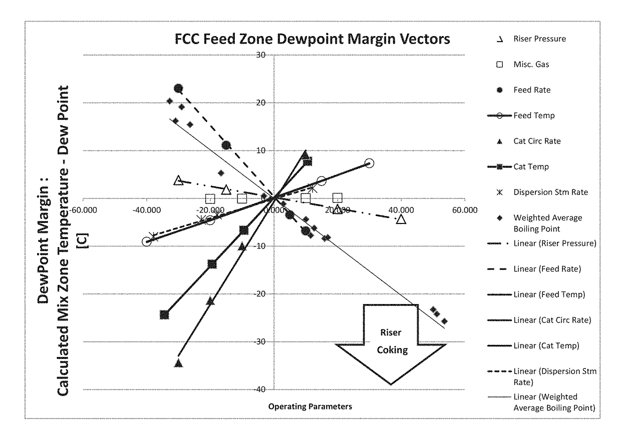
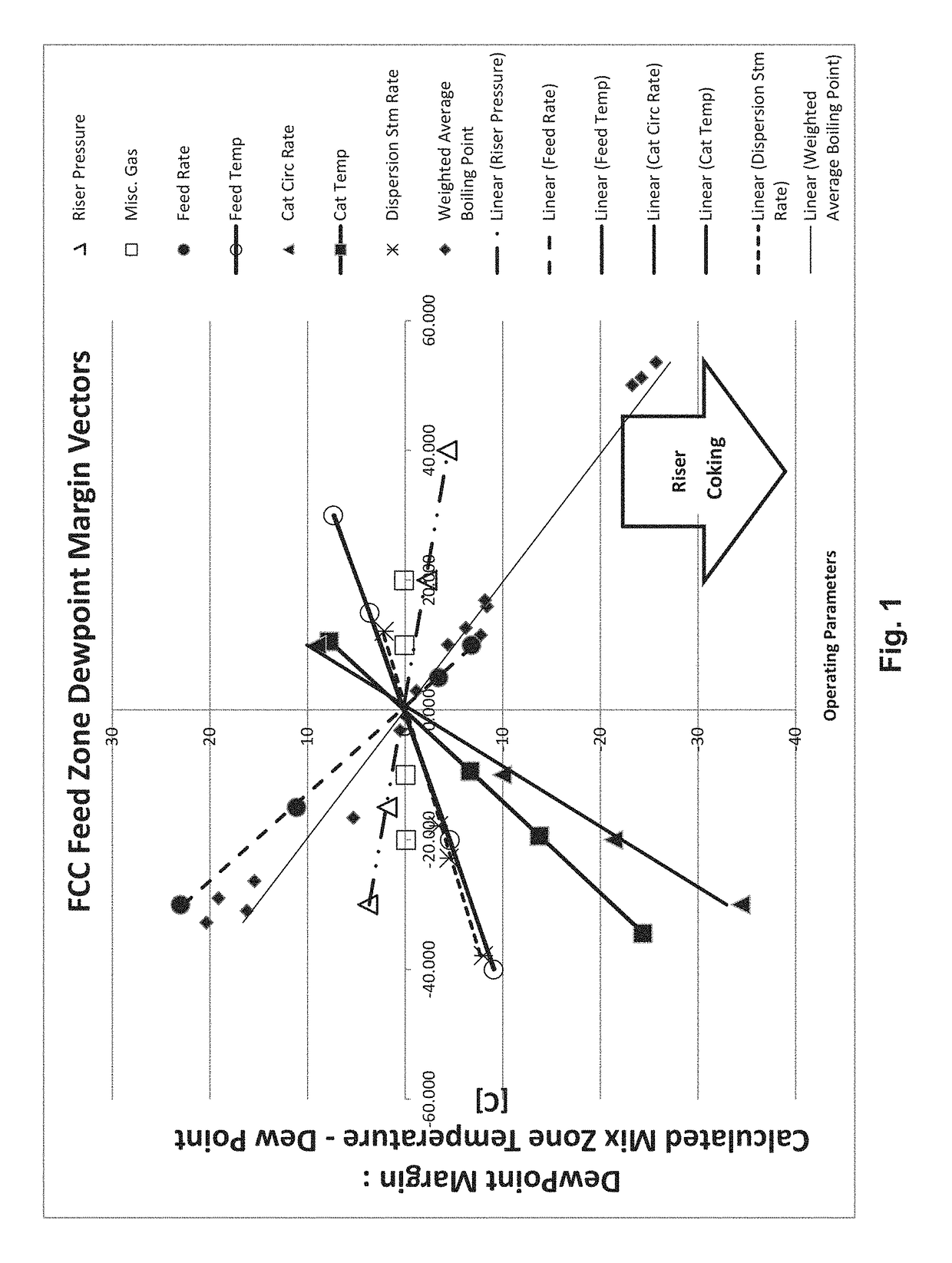
[0027]Riser coking is known as unique problem of FCC units that process heavier feeds, either gas oils with higher end points, resids as in Resid Catalytic Cracking or mixtures of gas oils and resids and has a lower reaction temperature in general in order to control the energy required for vaporization of the feed (approximately 70% of the energy consumed in the FCCU is for vaporization of the feed and this proportion is, of course, higher temperature for the less volatile feeds). Residual feeds, typically with end points above 540° C. (about 1000° F.) e.g. with at least 10 or 20 wt. pct. boiling above 450° C. (about 840° F.), not only require the greatest energy input for vaporization but also pose the greatest likelihood of incomplete vaporization and resultant riser coking. Industrial experience also recommends using more injection steam with the heavier feeds to assist in minimizing feed oil droplet size for improved contacting between the feed and hot catalyst from the regener...


PUM

PropertyMeasurementUnit
temperatureaaaaaaaaaa

Abstract

A method of predicting the tendency of a heavy oil feed to generate coke deposits in the FCC riser under a given set of operating parameters in the unit; thus, by utilizing operating parameters appropriate to the feed, the formation of coke deposits in the riser may be minimized. The margin between the theoretical dew point of the hydrocarbon feed established from unit operating parameters and the theoretical mix zone temperature in the feed injection zone of the unit is developed by applying a regression-derived linear model from multiple rigorous model runs. The mix zone of the unit is then operated at a temperature which reduces the level of riser coking predicted from this ascertainable margin or, at least, maintains it within levels which are predictable and acceptable.

Description

CROSS-REFERENCE TO RELATED APPLICATION[0001]This Non-Provisional patent application claims priority to U.S. Provisional Application Ser. No. 62 / 103,778, filed Jan. 15, 2015 and to U.S. Provisional Application Ser. No. 62 / 093,721 filed Dec. 18, 2014, herein incorporated by reference in their entirety.FIELD OF THE INVENTION[0002]The present invention relates to a method of reducing the incidence of coking, especially with heavy oil feeds, in the feed injection zone of fluid catalytic cracking units.BACKGROUND OF THE INVENTION[0003]The Fluid Catalytic Cracking (FCC) process is now the predominant process in the petroleum refining industry for the boiling range conversion of the high-molecular weight hydrocarbon fractions of petroleum crude oils to more valuable gasoline, olefins and other products which may be passed to other refining processes such as hydrocracking.[0004]Various types of FCC process unit (FCCU) exist with variant designs being offered by technology licensors in the in...

Claims


Application Information

Patent Timeline
Patent Type & Authority Patents(United States)
IPC IPC(8): C10G11/18
CPCC10G11/187C10G11/18C10G2300/107C10G2400/20C10G2300/1074C10G2300/1077C10G2300/708C10G2300/1033
Inventor SUGITA, MASAAKISMALLEY, CHRISTOPHER GORDONCUNNINGHAM, BRIAN A.FORBES, TIMOTHYFALCKE, TARRANT JAYSMITH, NICHOLAS E.
Owner EXXON RES & ENG CO