Optimised method and device loop combustion on liquid hydrocarbon feedstock

a technology of hydrocarbon feedstock and loop combustion, which is applied in the direction of combustion types, furnaces, capillary burners, etc., can solve the problems of large amount of metal oxides in contact, large amount of coke, and inability to separate still coked oxide particles from non-coked particles, so as to minimize energy dissipation in form of pressure drop, increase dilution evenness, and good heat dispersion

Inactive Publication Date: 2017-05-02
INST FR DU PETROLE +1
View PDF41 Cites 0 Cited by
  • Summary
  • Abstract
  • Description
  • Claims
  • Application Information

AI Technical Summary

Benefits of technology

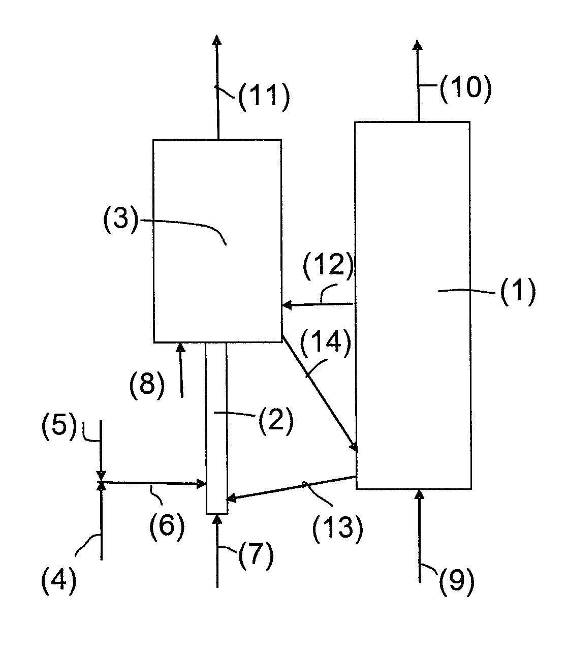
[0038]In the chemical looping combustion method according to the invention, vaporization of the liquid feed occurs upon contact with the hot metal oxide coming from the oxidation reactor or which has already been in contact with the hydrocarbons. Control of the liquid feed vaporization conditions for minimizing coke formation is provided by injecting the finely atomized liquid feed, preferably in form of droplets whose size is close to the size of the metal oxide particles.
[0051]Prior to contacting with the droplets, the void fraction of the suspension of metal oxide particles advantageously ranges between 0.5 and 0.9, preferably close to between 0.7 and 0.9 volume parts. The transport velocity of the particle suspension prior to contact with the liquid feed advantageously ranges between 0.3 and 5 m / s, preferably close to between 0.6 and 2 m / s. Under such conditions, the particles flow in a sufficiently dense manner through the transport zone, which allows good dispersion of the heat supplied by the particles to the droplets and uniform distribution of the coke resulting from the contact between the liquid and the particles among all the particles circulating in the transport zone.
[0052]After vaporization of a large part of the hydrocarbons injected into contact with the particles, the superficial gas velocity in the transport zone increases, which allows the metal oxides to be transported while minimizing the energy dissipation in form of pressure drop. In fact, the volume expansion of the gas phase causes dilution of the particles and acceleration thereof, which increases the dilution even further.
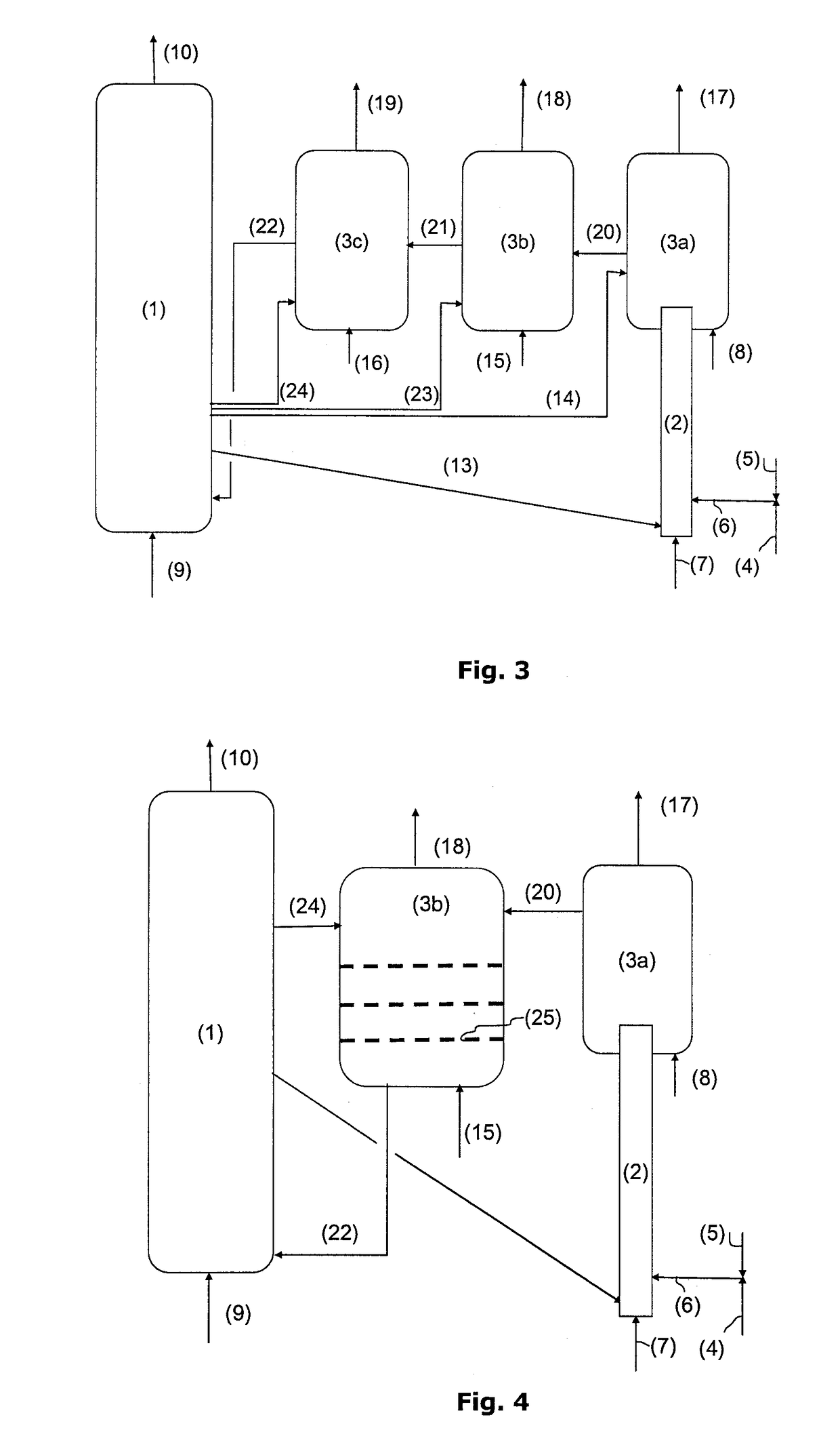
[0057]Thus, it is possible to introduce the gas and the particles together at the base of the fluidized bed of combustion zone (3) by equipping the upper part of transport zone (2) with means allowing dispersion thereof in the fluidized bed that are well known to the person skilled in the art (lateral vents on the reactor walls, widening and holed plate closing the upper part of the transport reactor, distribution of the gas and of the particles in the dense phase of the fluidized bed through optimized dimensioning of the holed plate orifices, etc.).
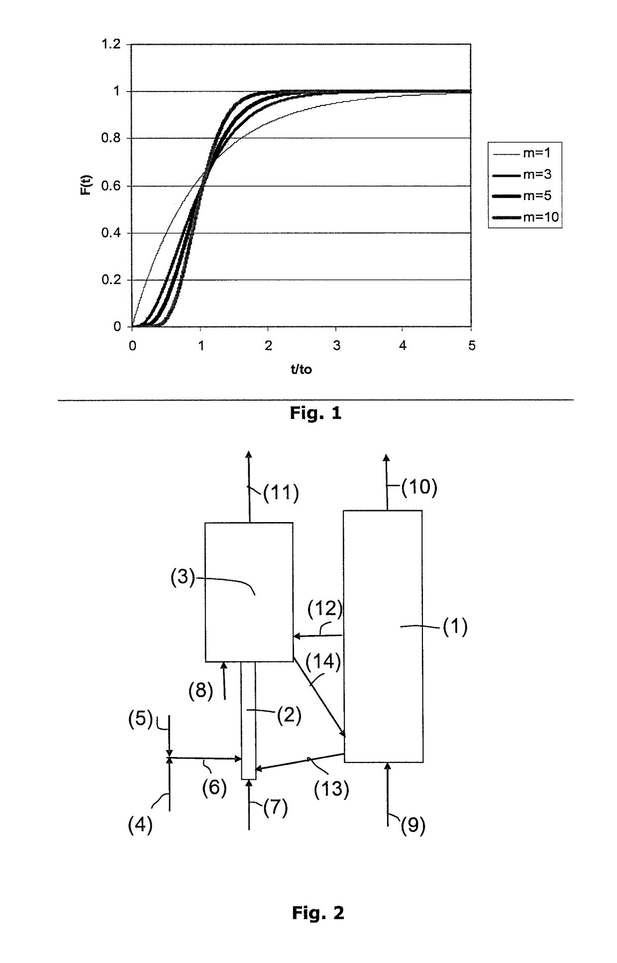
[0064]Now, in order to best optimize this reactor and to minimize the required reaction volume, it is advisable to have a flow that is close to the piston flow, which allows to have a homogeneous particle residence time and a narrow residence time distribution around the time required for the combustion reaction while minimizing the reaction volume.
[0069]Assuming that the coke deposited on the particles represents 45% of the hydrocarbon feed and considering that the vaporized fractions burn more rapidly than the coke, one can deduce therefrom that the CO2 emitted in the oxidation zone represents 14% of the CO2 emitted by the entire facility when using a perfectly stirred reactor in dense-phase combustion zone (3) following transport zone (2), whereas this value falls to less than 10% when using in dense-phase combustion zone (3) particle hydrodynamics corresponding to more than N=2 perfectly stirred reactors in series. This value falls to approximately 8% when using in dense-phase combustion zone (3) particle hydrodynamics corresponding to more than N=3 perfectly stirred reactors in series. The closer the particle hydrodynamics in the dense phase are to the piston flow in the dense-phase fluidized bed zone, the higher the CO2 capture efficiency of the facility.

Problems solved by technology

Implementing a chemical looping combustion method requires large amounts of metal oxides in contact with the fuel.
Upon contact between the liquid feed and the metal oxides, part of the feed is vaporized but coke settles on the particles due to the thermal cracking resulting from the liquid fuel being exposed to very high temperatures.
The heavier the feeds, the more they tend to form large amounts of coke.
Unlike the case where the feed is solid, it is indeed here impossible to consider separating the still coked oxide particles from the non-coked particles.

Method used


Image

  • Optimised method and device loop combustion on liquid hydrocarbon feedstock
  • Optimised method and device loop combustion on liquid hydrocarbon feedstock
  • Optimised method and device loop combustion on liquid hydrocarbon feedstock

Examples


examples

[0099]The performances of a combustion unit operating under chemical looping combustion conditions and treating a liquid feed consisting of a petroleum vacuum residue whose analysis is given below have been calculated.

[0100]

TABLE 1Wt. %C85.2H10.3N0.5S4

[0101]The metal oxide used is a titanium and iron ore capable of transferring during chemical looping combustion 1 wt. % oxygen in relation to the mass of particles used. The amount of residue treated by this unit is 30 kg / s. The particle circulation required to provide combustion of the residue is 34,000 t / h.

[0102]In a first case, the CO2 capture rate S (corresponding to the amount of CO2 recovered in the residue combustion zone through metal oxide reduction in relation to the total amount of CO2 emitted by the facility) is calculated for various unit configurations.

[0103]In example 1, the reaction zone considered for providing combustion of the residue through metal oxide reduction is a simple fluidized bed operating at a superficial...


PUM


Abstract

The invention relates to a device and to an improved method for chemical looping combustion of at least one liquid hydrocarbon feed, comprising: mixing the liquid feed with an atomization gas so as to feed it into a metal oxide particle transport zone (2), upstream from combustion zone (3), through atomization means (6) allowing to form finely dispersed liquid droplets in the atomization gas; vaporization of the liquid feed in form of droplets into contact with at least part of metal oxide particles in transport zone (2), the operating conditions in transport zone (2) being so selected that the superficial gas velocity after vaporization of the liquid feed is higher than the transport velocity of the metal oxide particles; sending all of the effluents from transport zone (2) to a combustion zone (3) allowing reduction of the metal oxide particles, said combustion zone (3) comprising at least one dense-phase fluidized bed. The invention can be advantageously applied to CO2 capture and energy production.

Description

FIELD OF THE INVENTION[0001]The invention relates to chemical looping combustion of liquid feeds, notably to a new technology for implementing this method.BACKGROUND OF THE INVENTION[0002]Chemical looping combustion of liquid feeds consists in contacting a liquid hydrocarbon feed with a metal oxide at high temperature. The metal oxide then yields part of the oxygen it contains, which takes part in the combustion of the hydrocarbons. After this combustion, the fumes contain predominantly carbon oxides, water and possibly hydrogen. In fact, it is not necessary to contact the air with the hydrocarbons, and the fumes are then predominantly made up of combustion gases and possibly of a dilution gas used for transport and fluidization of the particles (water vapour for example). It is thus possible to produce predominantly nitrogen-free fumes with high CO2 contents (>90 vol. %) allowing to consider CO2 capture, then storage. The metal oxide that has taken part in the combustion is then...

Claims


Application Information

Patent Timeline
Patent Type & Authority Patents(United States)
IPC IPC(8): F23D3/40B01J8/26B01J8/38F23C10/01F23C10/00F23C99/00F24V30/00
CPCF23C99/00B01J8/26B01J8/388F23C10/005F23C10/01B01J2208/00902F23C2900/99008Y02E20/346Y02E20/34Y02P30/40C10G11/18F23C10/00
Inventor GAUTHIER, THIERRYHOTEIT, ALIFORRET, ANN
Owner INST FR DU PETROLE
Why Eureka
Try Eureka