Surgical illuminator

a technology of illuminator and illuminator body, which is applied in the direction of treatment rooms, light and heating equipment, semiconductor devices for light sources, etc., can solve the problems of restricting, fatiguing, and uncomfortable fiber-optic tether of conventional systems, and achieves good light-emitting diodes life, no difficulty in touching the product during operation, and high optical efficiency of surgical illuminator

Active Publication Date: 2017-12-26
ENOVA ILLUMINATION INC
View PDF50 Cites 1 Cited by
  • Summary
  • Abstract
  • Description
  • Claims
  • Application Information

AI Technical Summary

Benefits of technology

[0006]The present invention provides a surgical illuminator that produces a clear, bright and adjustable spot without illumination anomalies and artifacts. The surgical illuminator is specifically designed for narrow depth of focus about the light emitting die and delivers a round spot on the viewing plane, with sharp edges. The optical efficiency of the surgical illuminator is high, and thus the spot is bright. The spot is free from the uneven illumination that has limited the acceptance of many light emitting diode based surgical illuminators. Further, the surgical illuminator is designed for thermal efficiency, yielding good light emitting diode life and no difficulties in touching the product during operation. Taken as a whole, the surgical illuminator produces performance that is on par with the fiber-optic illumination systems that surgeons are used to.
[0007]The enhanced performance of the surgical illuminator permits advancements in medical care. Surgeons have long found the fiber-optic tether of conventional systems to be uncomfortable, fatiguing, and restrictive. Thus, the surgical illuminator helps facilitate long surgeries. Further, many scenarios could benefit from surgical-suite quality lighting in a mobile situation. These scenarios include developing nations, emergency response, and field-military deployments.
[0008]The present invention provides a surgical illuminator with a round, adjustable beam, with high brightness and a clear field of view. The surgical illuminator produces an illumination spot this is free from illumination artifacts present on the light emitting diode die, which is the source of the illumination. Further, the surgical illuminator provides good cooling for the light emitting diode, yet provides that the beam adjustment mechanism not require that the user touch a hot surface.

Problems solved by technology

Surgeons have long found the fiber-optic tether of conventional systems to be uncomfortable, fatiguing, and restrictive.

Method used


Image

  • Surgical illuminator
  • Surgical illuminator
  • Surgical illuminator

Examples


Embodiment Construction

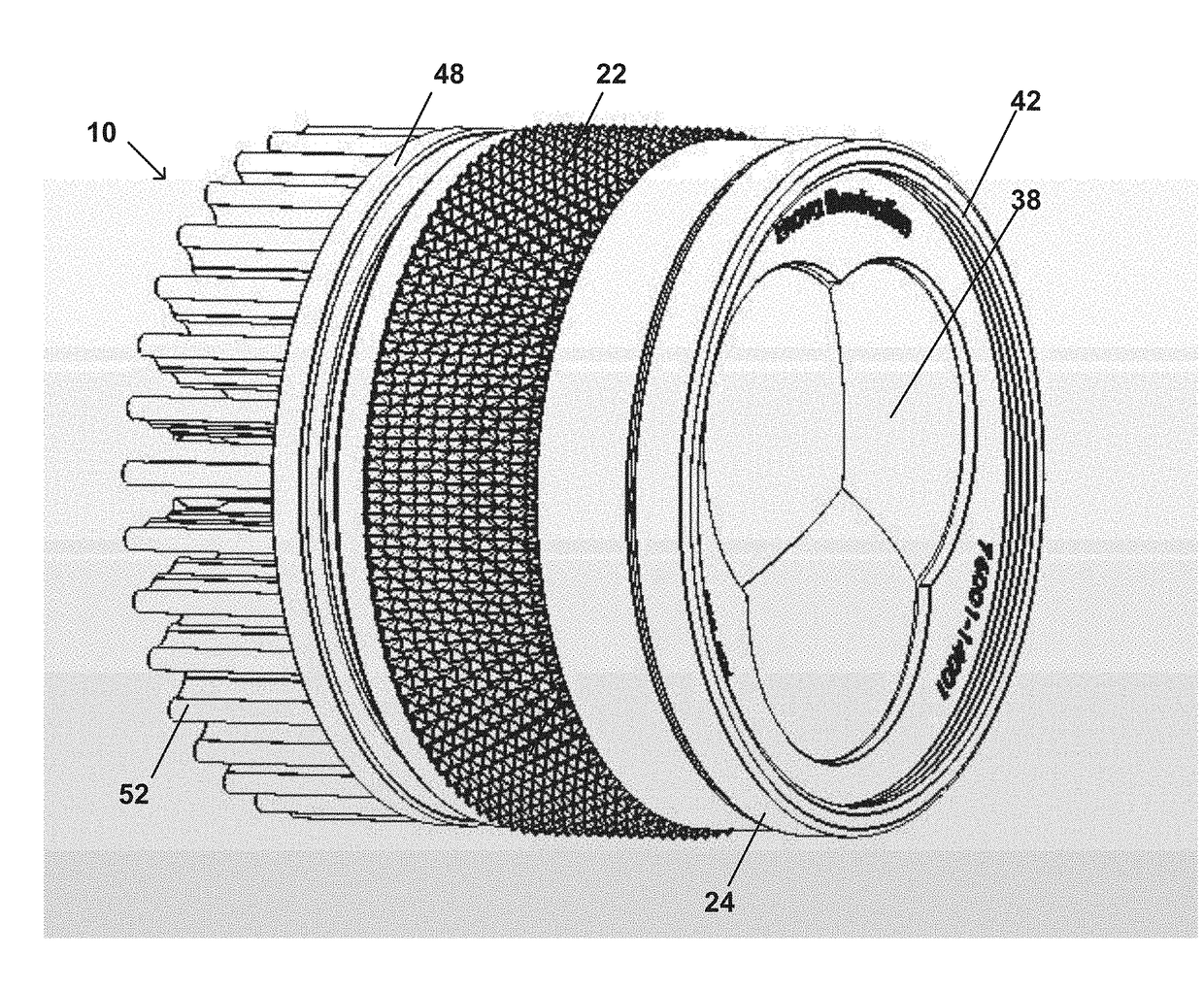
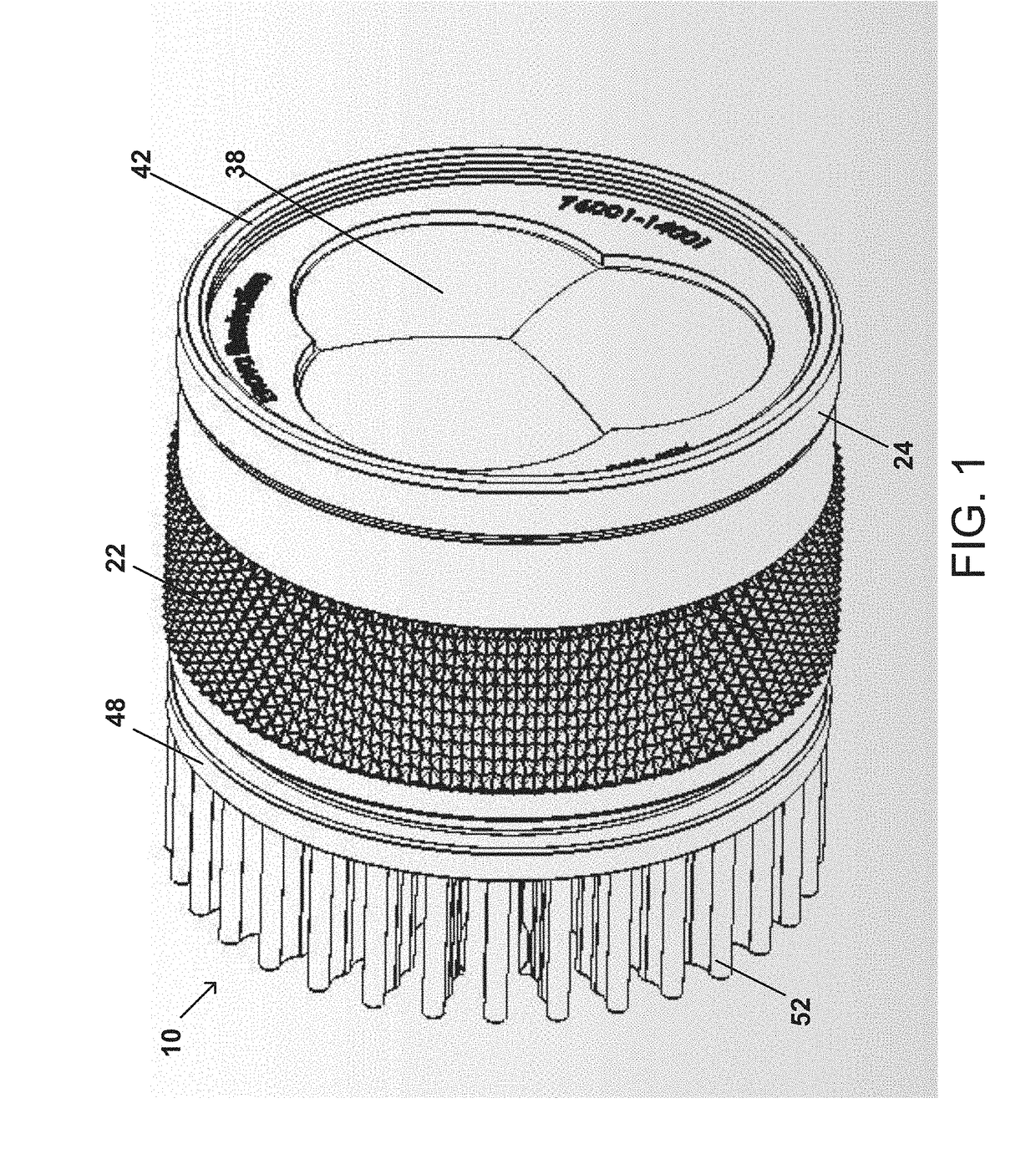
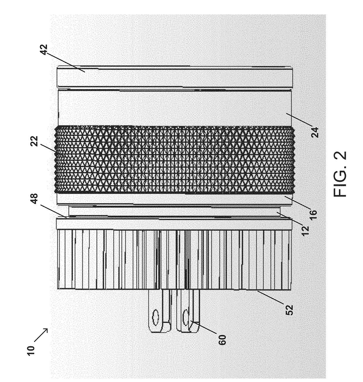
[0044]The present invention provides a surgical illuminator. The surgical illuminator includes a base, a guide barrel, a cam barrel, a grip ring, a lens barrel, a printed circuit board having three light emitting diodes, a triple aspheric lens, a first lens mask, a triple double-convex lens and a triple double-convex lens. Methods of using the surgical illuminator are also provided.

[0045]The following detailed description includes references to the accompanying drawings, which form a part of the detailed description. The drawings show, by way of illustration, specific embodiments in which the invention may be practiced. These embodiments, which are also referred to herein as “examples,” are described in enough detail to enable those skilled in the art to practice the invention. The embodiments may be combined, other embodiments may be utilized, or structural, and logical changes may be made without departing from the scope of the present invention. The following detailed description...


PUM


Abstract

The present invention provides a surgical illuminator. The surgical illuminator includes a base, a guide barrel, a cam barrel, a grip ring, a lens barrel, a printed circuit board having three light emitting diodes, a triple aspheric lens, a first lens mask, a triple double-convex lens and a triple double-convex lens. Methods of using the surgical illuminator are also provided.

Description

RELATED APPLICATIONS[0001]This application claims priority to U.S. Provisional Patent Application Ser. No. 62 / 323,408 filed Apr. 15, 2016, which is hereby incorporated by reference in its entirety for all purposes.BACKGROUND OF THE INVENTION[0002]High quality illumination is essential in medical applications, particularly in a surgical environment. Uneven illumination over the field of view may cause a surgeon to perceive problems that do not actually exist in the patient. Further, illumination anomalies and artifacts clutter and may distort the doctor's field of view, and may thus cause the doctor to miss details critical to the doctor's performance. Stray light beyond the desired illumination field distracts the doctor. Also, it is highly desirable to be able to adjust the spot of the illumination, so that only the area under consideration is seen by the doctor. Thus, medical professionals have long sought the best possible illumination in pursuit of the best possible outcomes.[00...

Claims


Application Information

Patent Timeline
Patent Type & Authority Patents(United States)
IPC IPC(8): F21V13/00F21V5/00F21V23/00F21L4/02F21V29/74F21V14/06F21W131/205
CPCF21V14/065F21L4/02F21V5/007F21V29/74F21V23/005F21Y2101/00F21W2131/205F21Y2115/10
Inventor TEDER, REINHEEGAARD, ROGER WILLIAM
Owner ENOVA ILLUMINATION INC
Why Eureka
Try Eureka