
Hearing aid device with positioning guide and hearing aid device system

a positioning guide and hearing aid technology, applied in the field of hearing aid devices, can solve the problems of difficulty for hearing aid users to place hearing aid devices, and the hearing aid user will not have an optimal hearing experience, and achieve the effect of preventing potential damage to the structure of the ear canal

Inactive Publication Date: 2018-01-02
OTICON
View PDF30 Cites 2 Cited by
  • Summary
  • Abstract
  • Description
  • Claims
  • Application Information

AI Technical Summary

Benefits of technology

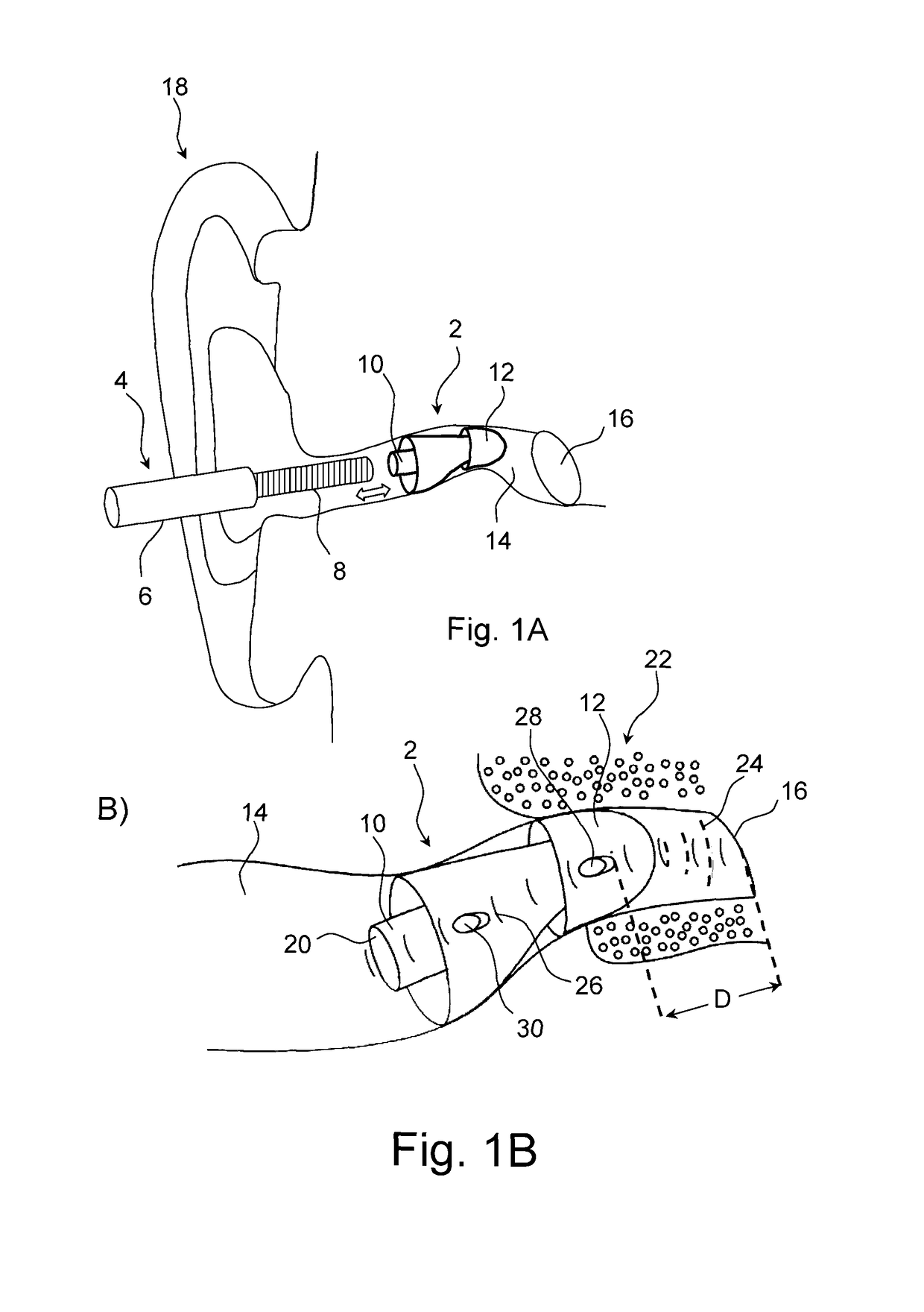
[0011]Hereby, the hearing aid device (by means of the processing unit) can detect if and when the hearing aid device is positioned in a correct position in the ear canal. In this way, the hearing aid device can “guide” the hearing aid user in a manner that facilitates that an optimum position of the hearing aid device can be achieved.
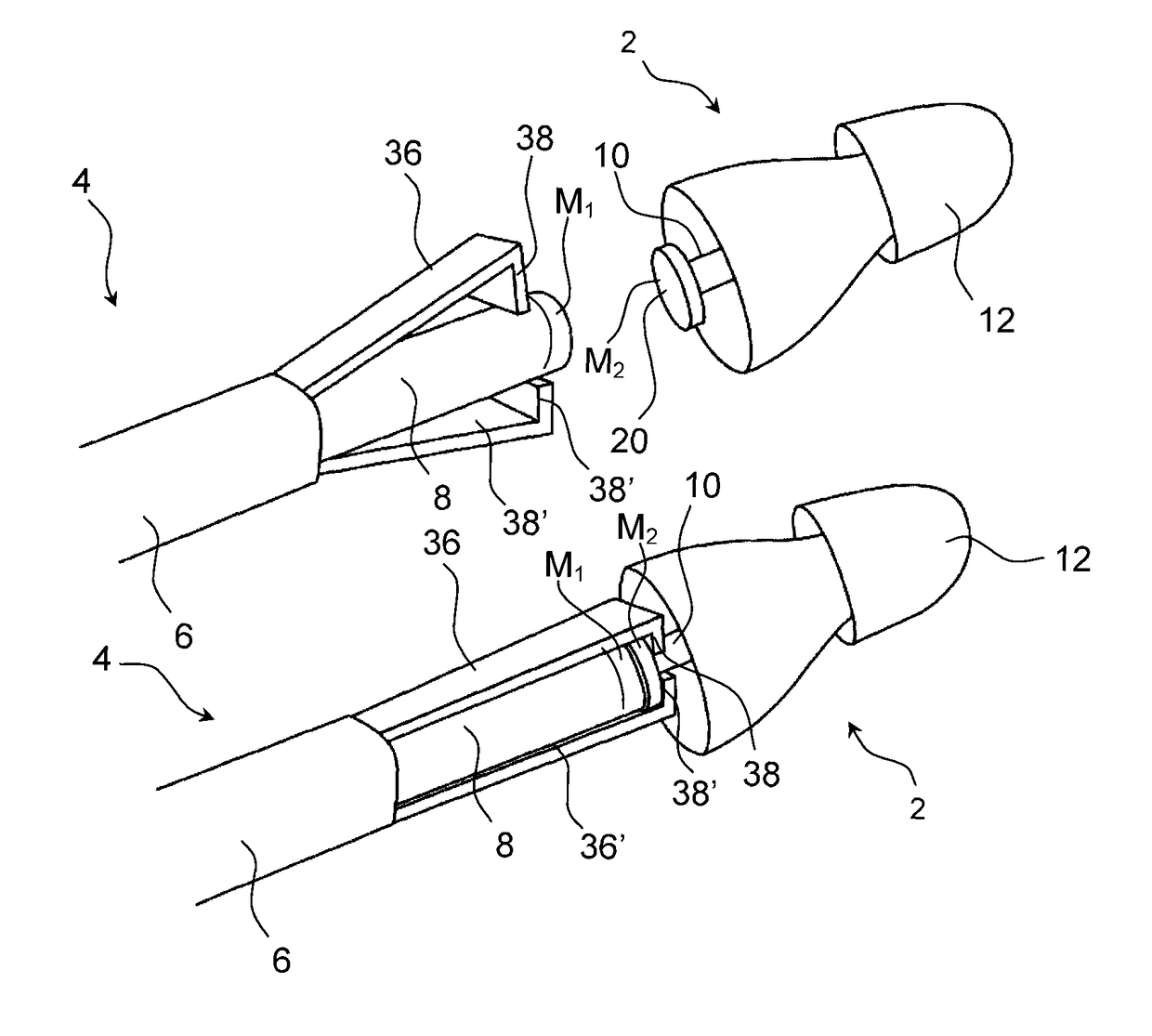
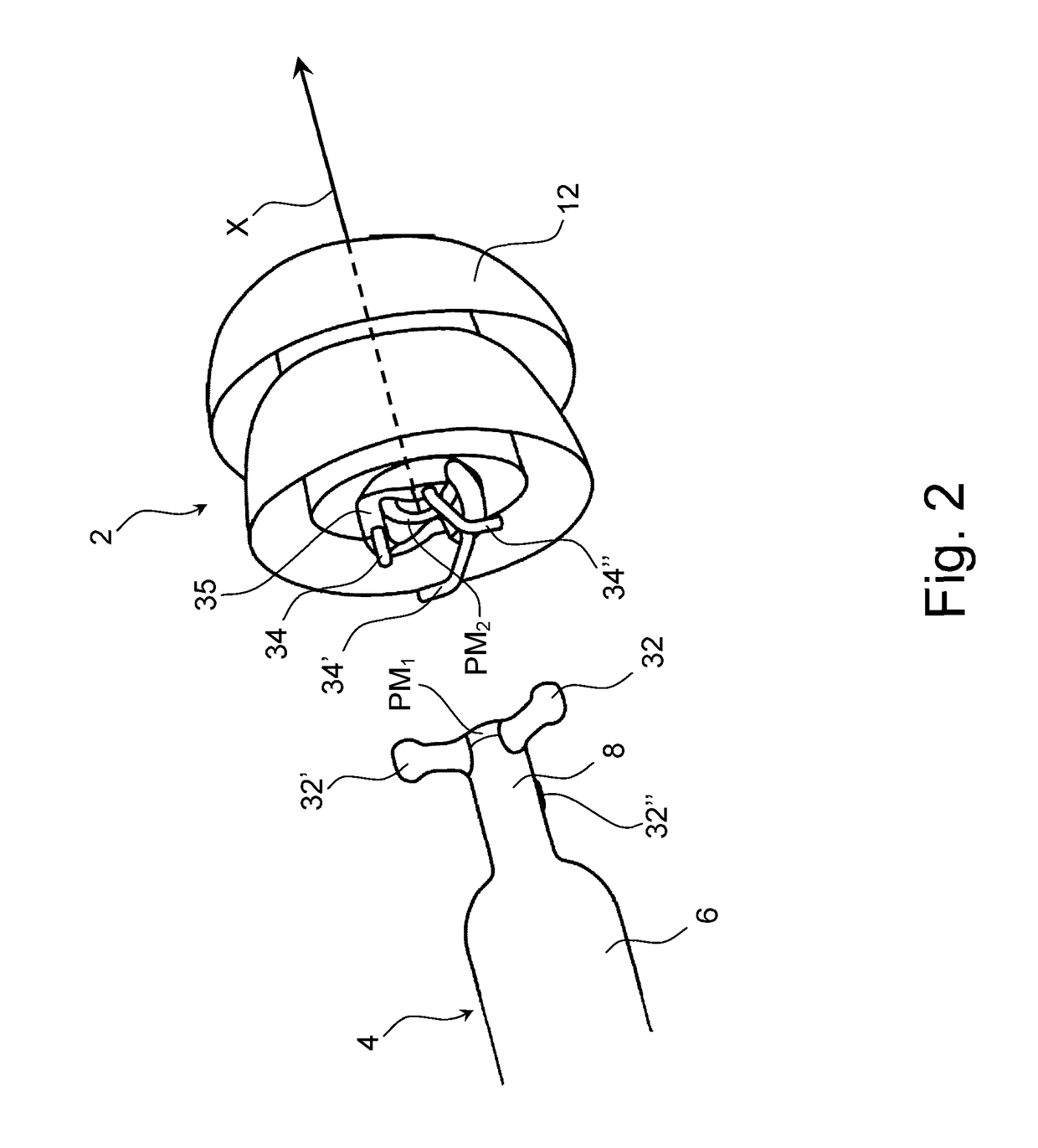
[0053]In effect the hearing aid positioning system aids in correct positioning of the hearing device, in that an insertion tool of the system guides the hearing device into the ear canal by control of a user, while at the same time the user is guided by a positioning determination of a processing unit of the hearing device to determine the correct position in relation to at least depth into the ear canal. The concurrent functionality and detection of the positioning, as provided by the processing unit of hearing aid upon insertion in the ear canal is in accordance with the previously described aspects. By the cooperation between the tool for insertion and the positioning detection, a hearing aid wearer is informed of correct placement of the hearing aid in the ear canal, and potential damage to structures of the ear canal is prevented.

Problems solved by technology

It is difficult for the hearing aid user to place the hearing aid device in the optimum position in the ear canal, because the user cannot see when the optimum position is achieved.
If the hearing aid device is not placed in the correct position in the ear canal, the hearing aid user will not have an optimum hearing experience.

Method used


Image

  • Hearing aid device with positioning guide and hearing aid device system
  • Hearing aid device with positioning guide and hearing aid device system
  • Hearing aid device with positioning guide and hearing aid device system

Examples


Embodiment Construction

[0062]The detailed description set forth below in connection with the appended drawings is intended as a description of various configurations. The detailed description includes specific details for the purpose of providing a thorough understanding of various concepts. However, it will be apparent to those skilled in the art that these concepts may be practiced without these specific details. Several aspects of the apparatus are described by various blocks, functional units, modules, components, steps, processes etc. (collectively referred to as “elements”). Depending upon the particular application, design constraints or other reasons, these elements may be implemented using electronic hardware, computer programs, or any combination thereof.

[0063]The electronic hardware may include microprocessors, microcontrollers, digital signal processors (DSPs), field programmable gate arrays (FPGAs), programmable logic devices (PLDs), gated logic, discrete hardware circuits, and other suitable...


PUM


Abstract

A hearing aid device configured to be partly or fully inserted into the ear canal of a user is disclosed. The hearing aid device comprises a receiver (loudspeaker) adapted to generate and send an air-borne acoustic signal towards the eardrum when the hearing aid device is partly or fully inserted into the ear canal. The hearing aid device further comprises a microphone configured to receive acoustic signals. The hearing aid device comprises a processing unit configured to determine if the hearing aid device is positioned in a correct position in the ear canal on the basis of the acoustic signals received by the microphone.

Description

FIELD OF INVENTION[0001]The present disclosure relates to a hearing aid device configured to be partly or fully inserted into the ear canal of a user. More particularly, the present disclosure relates to a hearing aid device that is easy for the user of the hearing aid device to place in the correct position in the ear canal.BACKGROUND[0002]Hearing aid devices that can be placed completely or almost completely in the ear canal are very popular, because they are suitable for most types of hearing losses and are relatively discreet. Some of these In-The-Ear (ITE) hearing aid devices can be placed deep in the ear canal.[0003]It is difficult for the hearing aid user to place the hearing aid device in the optimum position in the ear canal, because the user cannot see when the optimum position is achieved. This is particularly the case with hearing aid devices, which are placed deep in the ear canal. If the hearing aid device is not placed in the correct position in the ear canal, the hea...

Claims


Application Information

Patent Timeline
Patent Type & Authority Patents(United States)
IPC IPC(8): H04R25/00G01S15/08G01S15/88
CPCH04R25/305G01S15/08G01S15/88H04R25/652H04R25/604H04R2460/17H04R2225/023H04R2225/025H04R25/45H04R25/60H04R2225/61
Inventor OLSEN, THOR HOJLUNDKOCH, POVLPEDERSEN, TROELS HOLMNIELSEN, CLAUSLAUGESEN, SORENRASMUSSEN, KARSTEN BOSOMMER, PETERCHRISTENSEN, KARE TAISPETERSEN, SVEND OSCARJOHANSEN, JORNSEVERIN, BENTFRANTZEN, JANJORGENSEN, LARS LUNDJENSEN, GLENNTHOMSEN, ANDERS HOJSGAARDMUNK, STEEN MICHAELOLSEN, HENRIK LODBERGHEBSGAARD, ANDERSBHAT, VIJAY KUMAR
Owner OTICON
Learn More