Masonry block system

a masonry block and block system technology, applied in the field of masonry blocks, can solve the problems of difficult to secure the insulation within the block, difficult to provide the insulation of the masonry block easily and economically, etc., and achieve the effects of less expensive, greater insulation value, and greater strength and rigidity

Active Publication Date: 2018-01-09
GENEST CHRISTOPHER +1
View PDF17 Cites 8 Cited by
  • Summary
  • Abstract
  • Description
  • Claims
  • Application Information

AI Technical Summary

Benefits of technology

[0006]The masonry block according to the invention, which includes a stretcher block, an end block, a corner block, a half block, and a corner block, has chambers or cavities for receiving insulation and re-bar. The layout of the chambers and recesses in the masonry block is such that, when the blocks are laid on bond, the re-bar may be inserted in the horizontal and vertical directions for rectangular grid reinforcement. Additional chambers with small notches are provided in the block for receiving and securing insulation material. Small notches for line pins are also provided in front and rear faces of the blocks. These blocks are used to construct a wall without the use of mortar and, when a course of blocks is put in place, conventional line pins may be inserted in these notches and a line inserted through the pins and pulled taut, thereby ensuring that the block formation is straight. A narrow chamber on the front face of the block allows electrical cables to be placed within the wall such that an electrical box may be placed flush against the wall. A wall constructed with this masonry block thus has greater strength and rigidity than a conventional masonry block wall and a greater insulation value. The wall construction is less expensive than conventional construction and has a positive environmental impact, because of a reduced amount of energy that is required to heat or cool a building constructed with the masonry block according to the invention.

Problems solved by technology

The fact that re-bar is inserted in masonry blocks makes it difficult to easily and economically provide a masonry block with insulation.
It is also difficult to secure the insulation within the block.

Method used


Image

  • Masonry block system
  • Masonry block system
  • Masonry block system

Examples


Embodiment Construction

[0044]The present invention will now be described more fully in detail with reference to the accompanying drawings, in which the preferred embodiments of the invention are shown. This invention should not, however, be construed as limited to the embodiments set forth herein; rather, they are provided so that this disclosure will be complete and will fully convey the scope of the invention to those skilled in the art.

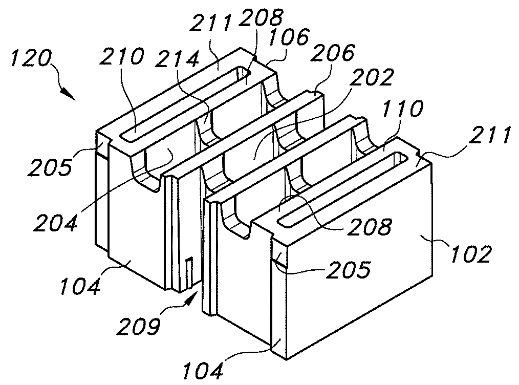
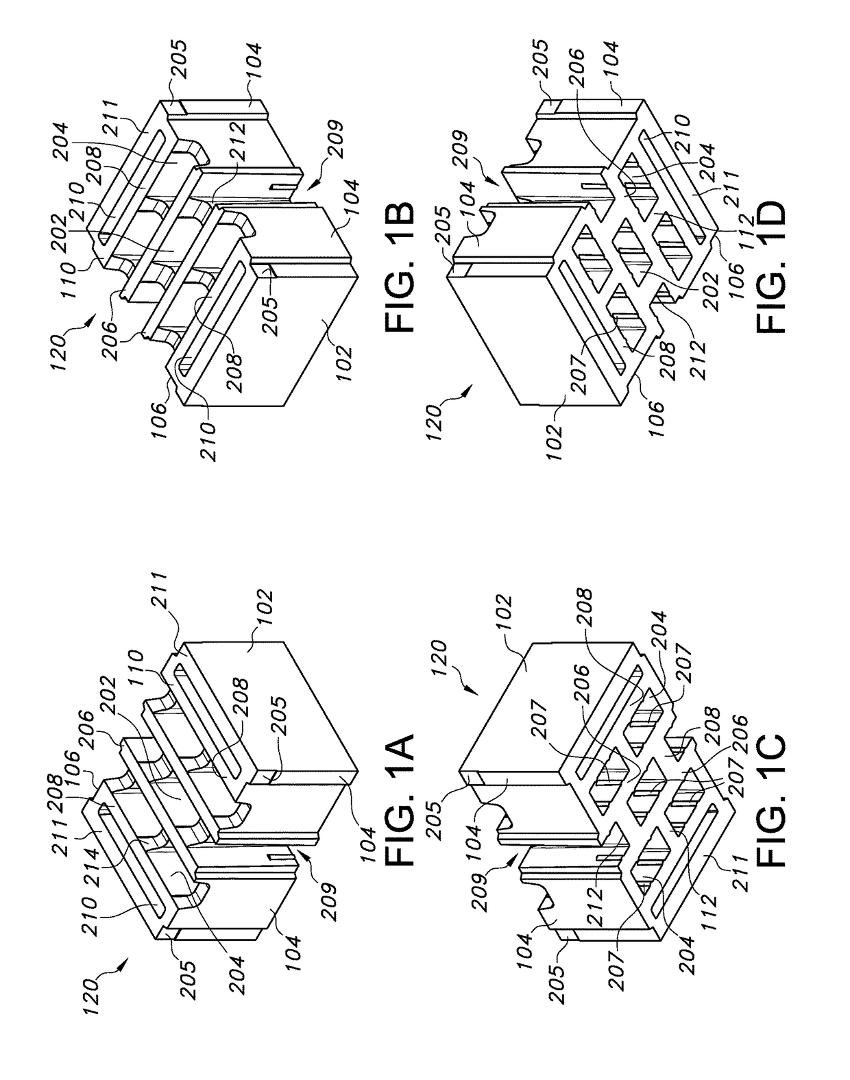
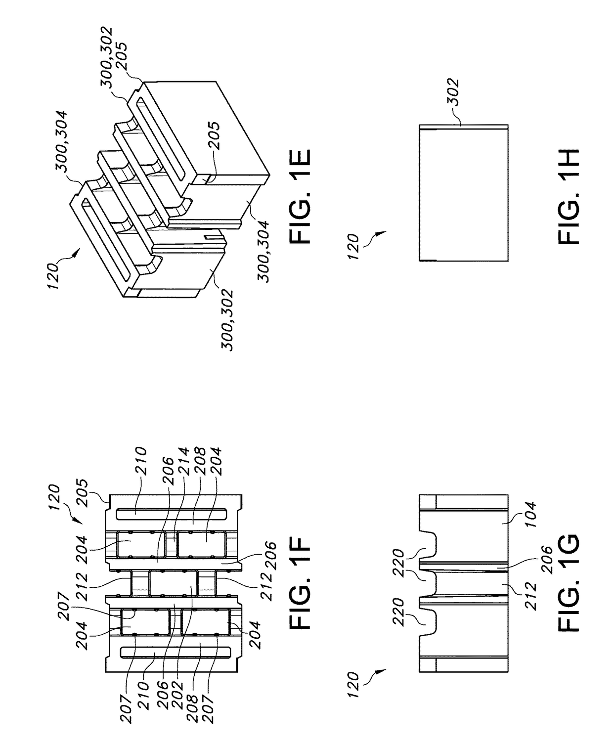
[0045]The invention is a masonry block 100 for building masonry block walls. The masonry block 100 is constructed to receive insulation material. The insulation material may be in any suitable form, for example, a rigid foam block, batting, or spray foam insulation.

[0046]The term “masonry block 100” is a general term for the block according to the invention and includes a stretcher block 120, a half block 140, an end block 160, a corner block 180, and a spacer block 190. Incorporated into each block 100 are one or more chambers or recesses 200 for receiving insulation am...


PUM


Abstract

A masonry block having chambers and cavities that form recesses in the block such that, when the blocks are laid on bond, re-bar may be inserted in horizontal and vertical directions for rectangular grid reinforcement, and the wall may be constructed without the use of mortar. The masonry block includes a stretcher block, end block, and a half-block and each block block has recesses for receiving insulation, re-bar, and / or a line pin.

Description

BACKGROUND INFORMATION[0001]Field of the Invention[0002]The invention relates to a masonry block. More particularly, the invention relates to a building block having cavities for insulation.[0003]Discussion of the Prior Art[0004]Masonry blocks are frequently used for building walls of residential and commercial structures. In a conventional masonry block wall, the blocks are laid on bond, that is, the one block covers one half of two blocks below it, so that the vertical joint formed by adjacent blocks in one row does not align with a vertical joint similarly formed in a previous row. The blocks typically have passageways that allow reinforcement bars (hereinafter referred to as “re-bar”) to be inserted through the blocks to form a rectangular grid. For example, every four feet in the horizontal direction a re-bar is inserted in the vertical direction through the rows of block in that vertical four-foot length, and every four feet in the vertical direction a re-bar is inserted in th...

Claims


Application Information

Patent Timeline
Patent Type & Authority Patents(United States)
IPC IPC(8): E04B2/18E04B2/52E04B2/46E04C1/39E04B2/02
CPCE04C1/39E04B2/46E04C1/397E04B2/52E04B2002/0293E04B2002/023E04C1/41
Inventor GENEST, CHRISTOPHERGENEST, MATTHEW
Owner GENEST CHRISTOPHER
Why Eureka
Try Eureka